Concept

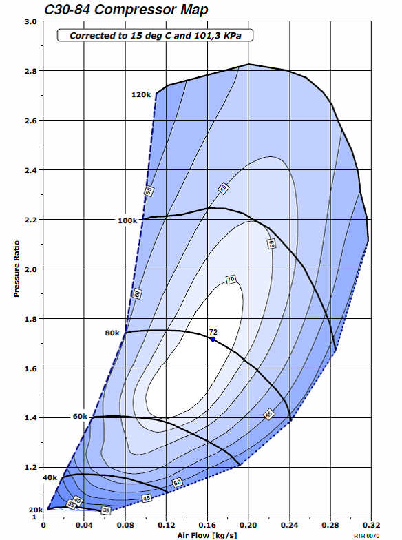
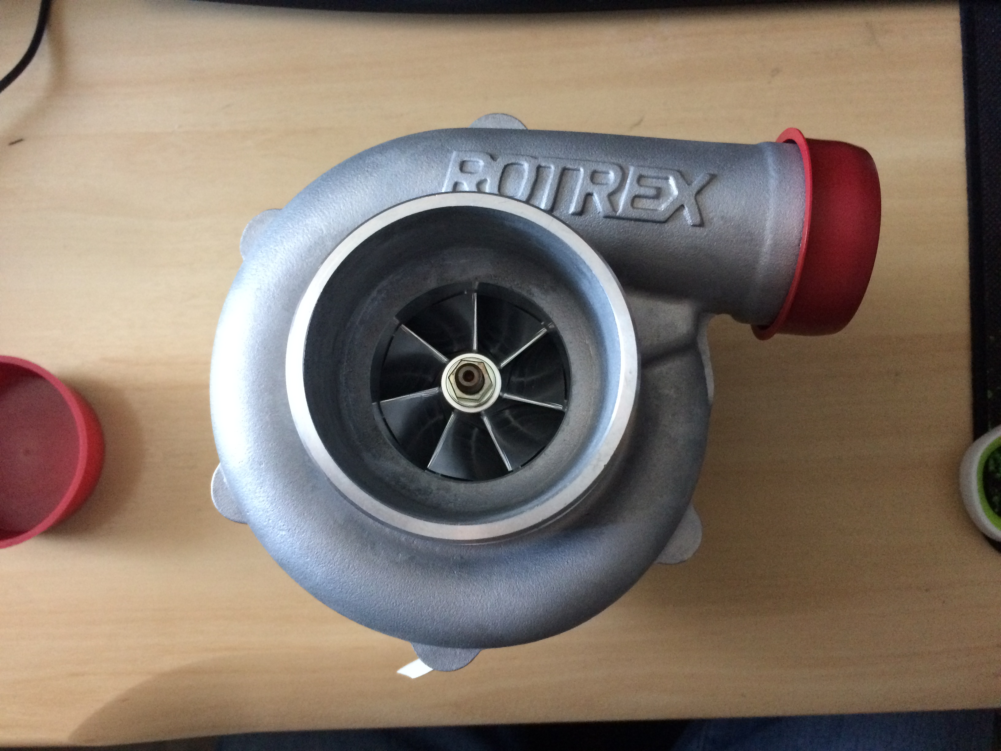
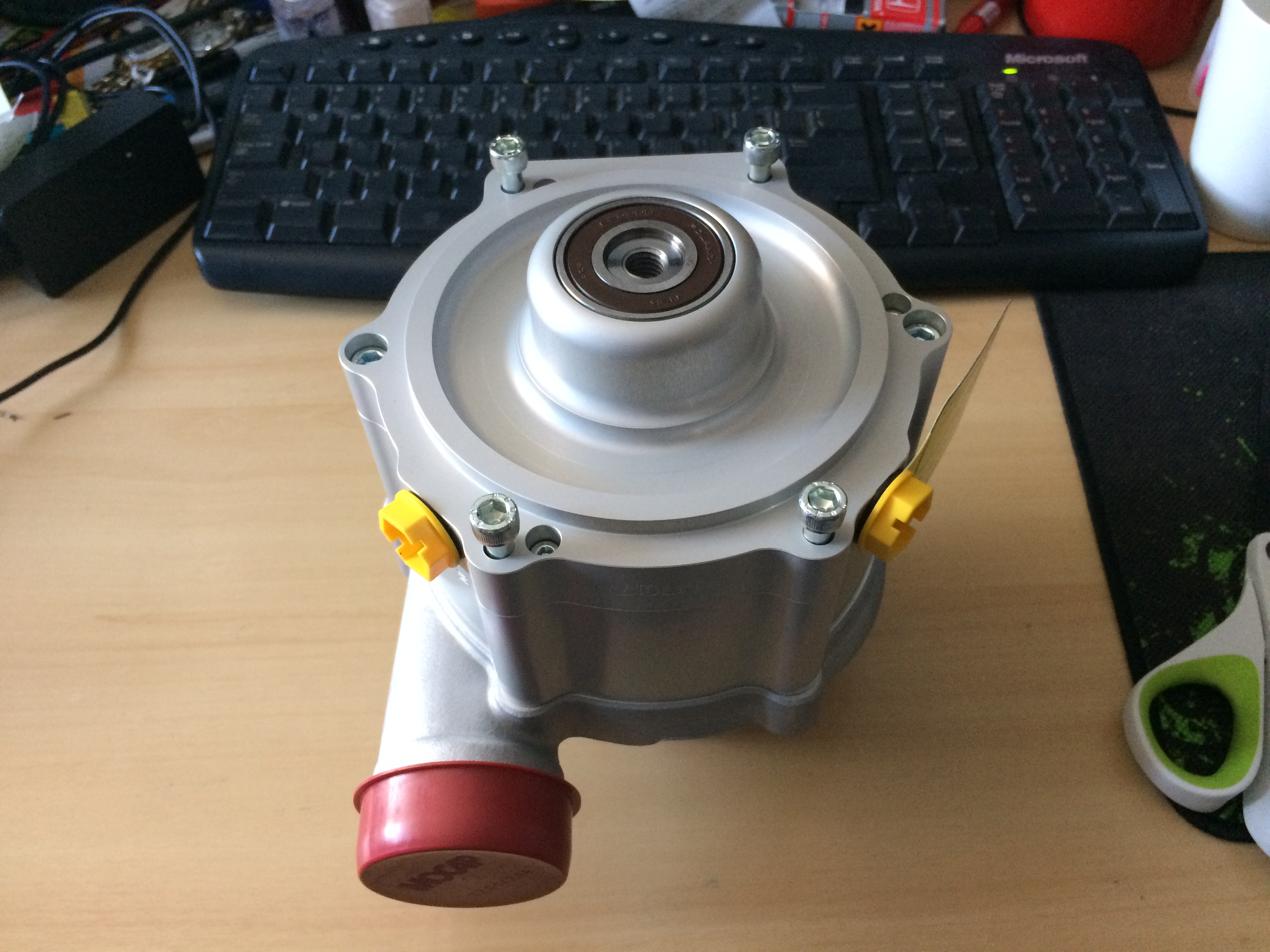
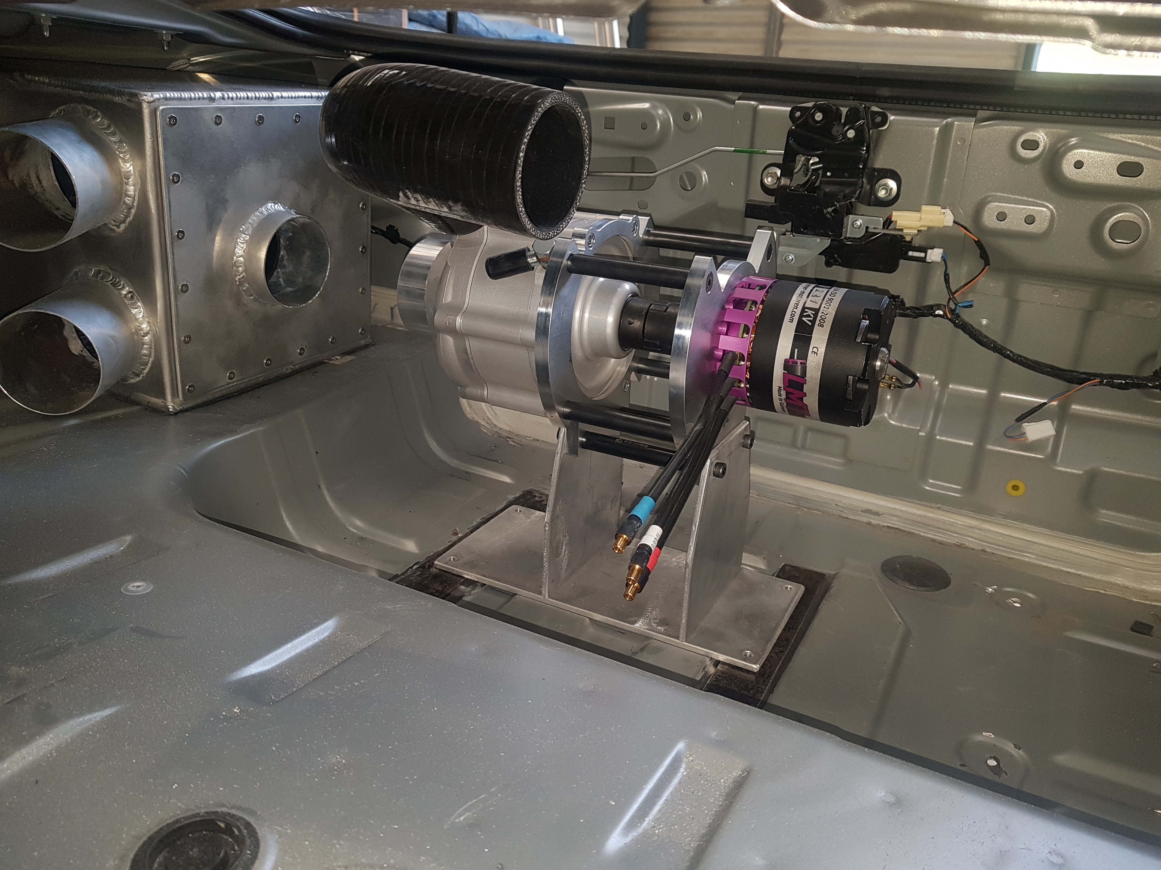
Develop an electrical motor driven centrifugal supercharger for the Mazda MZR (Ford Duratec) 2.0 litre engine with the capability to deliver a minimum 0.75 bar (11.0 psi) at redline and full load.  This would include the ability to program any boost level at any throttle, engine speed, and engine load.

The intent is for the system only to be run during relatively short motor sport events, and when not in use the system will be turned off and the compressor bypassed.  A separate higher voltage battery would run the system and will be charged of the alternator when the system is not in use.

Advantages:

  • Zero turbo lag, boost on demand
  • Boost infinitely variable at any engine speed and load
  • Power usually used to drive supercharger from crankshaft is available to the wheels.  System powered from dedicated battery
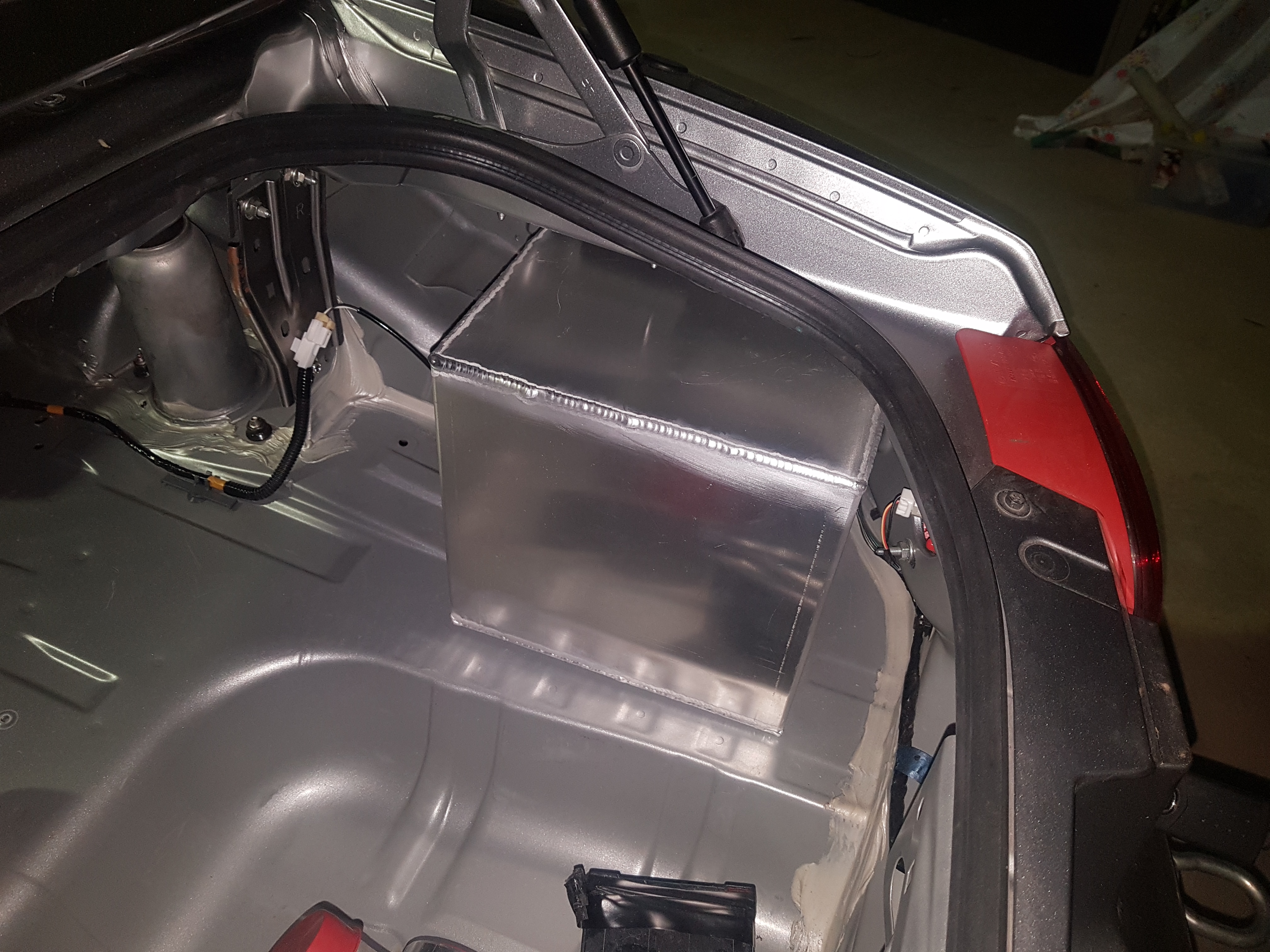
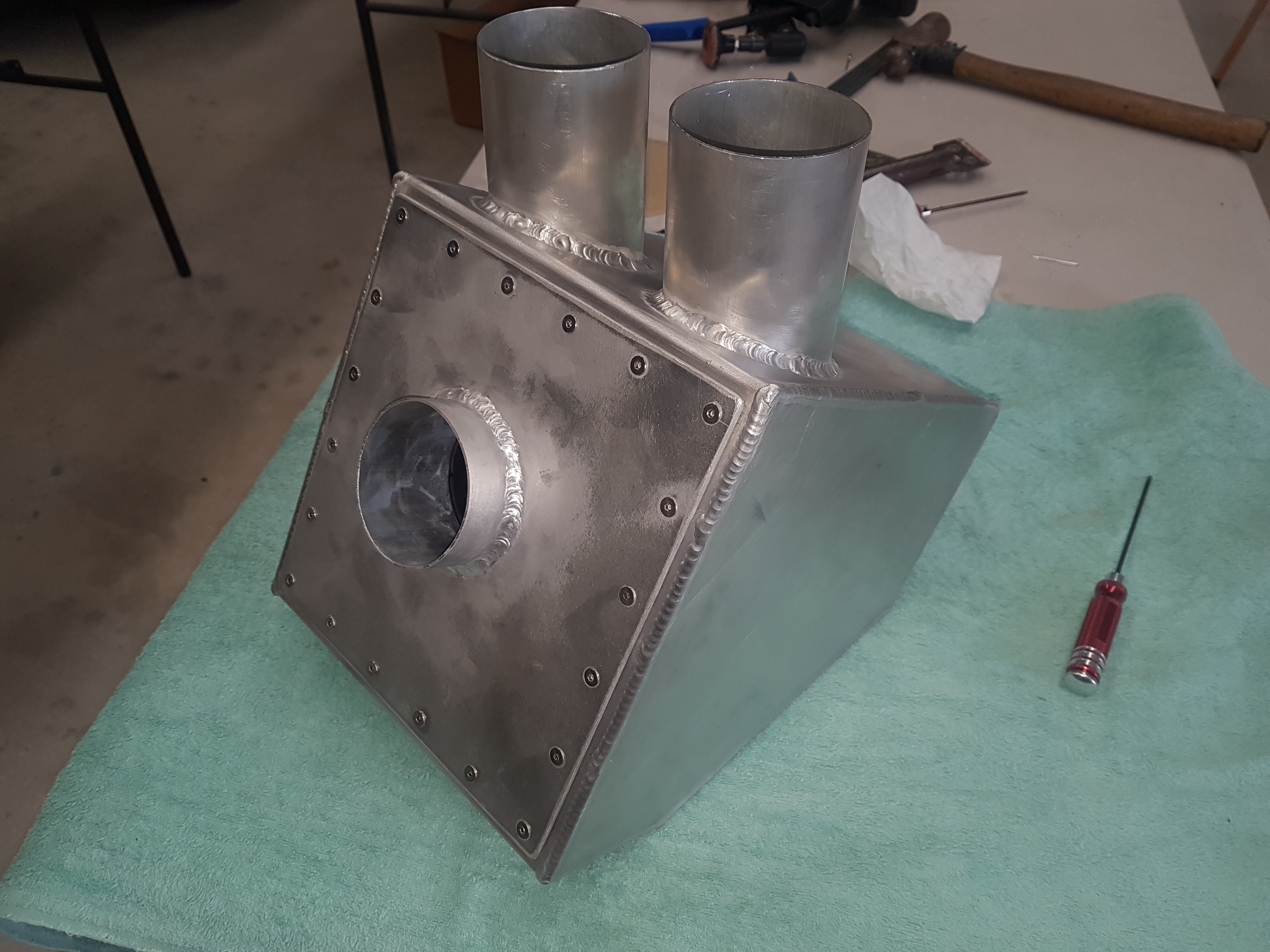
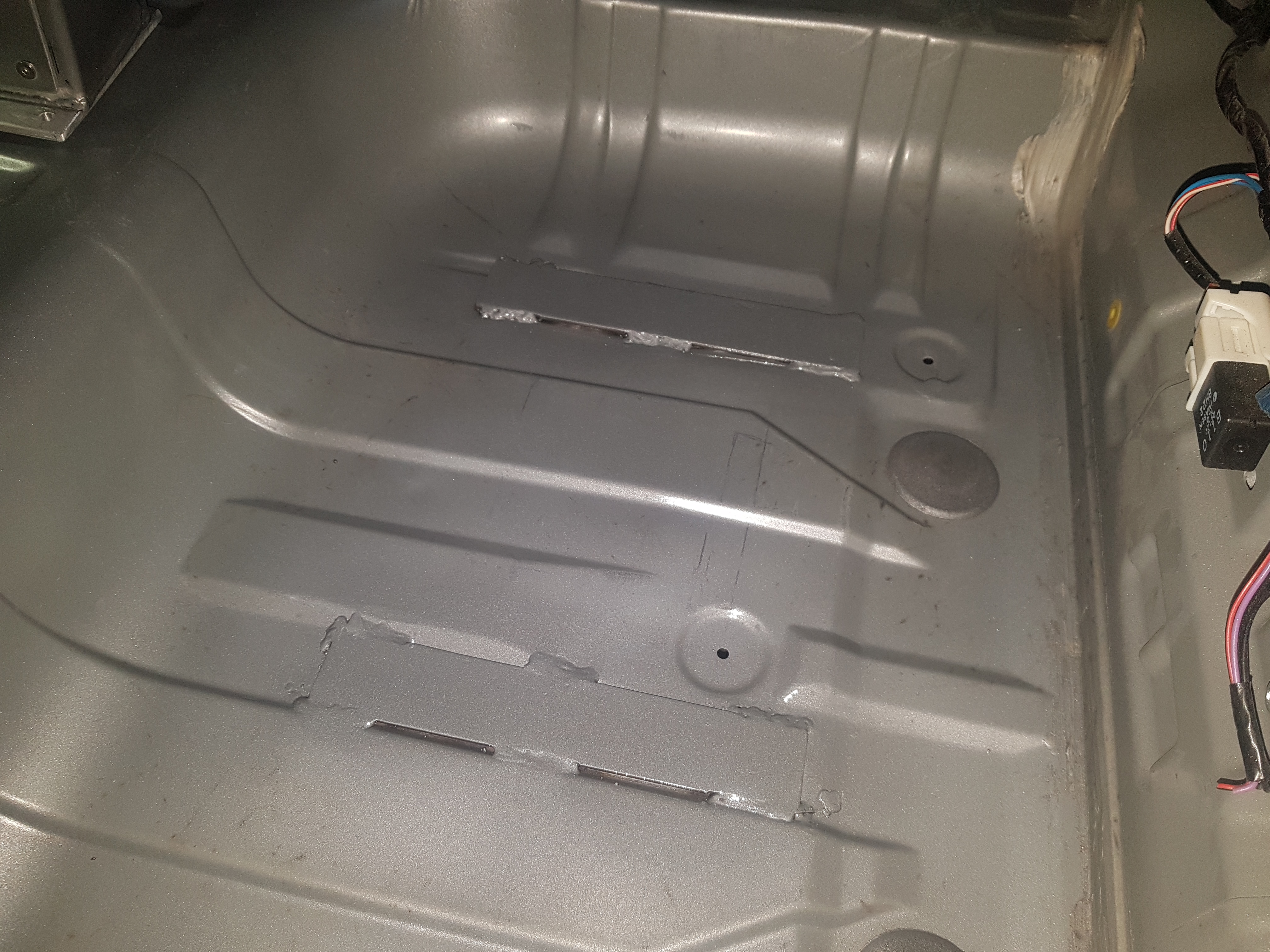
  • Supercharger can be mounted anywhere in the vehicle.  In this case system mounted in rear of vehicle due to packaging and to help with weight distribution

Disadvantages:

  • Extra weight due to addition of electric motor and battery pack
  • Cannot be run continuously (system needs to be shut down for battery pack to be recharged)
  • Complexity

Background

A couple of years back I purchased MX-5 NC to participate in club motorsport.  After a year of racing, during which time the suspension, brakes, wheels, tyres, and exhaust had the usual treatment I was starting to think about more power.  I wasn’t keen on turbo charging so the different supercharger options on the market were investigated.

The conclusion was that roots-type positive displacement superchargers were a good choice for autocross style motorsport were full power is required from low rpms to pull out of tight corners, but weren’t great in the higher rpm range.  Whereas the centrifugal superchargers have a better adiabatic (thermal) efficiency and are better for track use when the engine speed can be kept above 4000 rpm (as the boost pressure increase as the square of the engine speed).

As the vehicle is used for a wide variety of motorsport why not have the best of both worlds, boost down low and up high with good adiabatic efficiency.  Plus the ability to adjust boost level and delivery to match the course and event.

Mazda MX-5 NC 2011

The Compressor

After some research the Rotrex C30-84 supercharger was selected.  This was due to:

  • The compressor map being a good fit for the pressure ratios and mass flow rates required
  • Traction drive system provide a high 1 : 9.49 ratio allowing the electric motor to operate at speeds up to 10,000 rpm
  • Self-contained oil system (can be mounted anywhere in vehicle)
  • Packaging (compactness)
  • High mechanical and adiabatic efficiency
  • Low vibration and noise
90,000 rpm on the impellor should provide 11 psi at 2.55 g/s mass air flow
Front View of Rotrex supercharger showing intake and impellor
Back view of Rotrex supercharger showing input shaft


The Electric Motor

The mention of electrical superchargers conjures up thoughts of the dodgy offerings on ebay.  From initial calculations, 10 kW of mechanical power (equalling 12 kW of electrical power) would be required from the electric motor to produce 8.0 psi at redline and full load (this equates to a mass air flow of 2.55 g/s).

The problem with almost all electric supercharger systems currently available is voltage.  That is running the electric motor of the vehicles 12 V battery.  To generate 12 kW (16 HP) at 12 V requires 1000 A.  This is not practical so voltage must be increase.  For this project a battery voltage of 60 V was selected.

Next step was to select a motor.  The motor had to be small and light with a high power to weight ratio.  The Lehner Motoren Technik (LMT) Torqstar 3 was selected.  LMT are a company out of Germany that design and manufacture the highest quality brushless DC electric motors.  LMT Torqstar motors are hand made to order in one of 37 different winding configurations.  This allowed the motor operating RPM range to be match perfectly to the required operating speed of the compressor.  The motor was ordered with water cooling option to keep temperatures in check.

The LMT Torqstar 3

The selected winding of the LMT Torqstar 3 is rated for a maximum current of 290 amps giving a maximum electrical power input of approximately 15 kW and weighs in at 1.9 kg.

Had to take the motor apart to have a look. The stator core has a super fine laminations. It looks like the windings are pressed into rectangular stator slots held in place by the resin. The individual windings are then connect together using a PCB. The rotor is 20 pole (10 pairs of magnets).

Motor stator and windings
Stator laminations and surface finish is impressive
20 pole rotor

The E-charger Assemble

Time to bring the two together

The plan from the start of the project was for the motor to direct drive the compressor.  The selection of the Rotrex compressor and LMT motor electric motor made this possible.  The next step was to design a system to connect the two so that the motor could drive the compressor.  For power transmission the L Type standard jaw coupling was selected.  Then mounting plates were designed to adapt the motor to the supercharger and also provide a means for mounting the assemble in the vehicle.

3D design of mounting plates (thanks to Huey for assisting with drafting)
Finished CNC machined mounting plates

Mounting plates were machined from 10mm thick 6061 Aluminium plate.  The six stand offs between the two plates are made of hardened steel and counter sunk for additional strength.

Assemble completed and ready for install
Silicon tube is for liquid cooling of electric motor stator and windings

Final mass of the electric supercharger assemble is 8.5 kg.

Electronic Speed Controller

The selected electronic speed controller (ESC) for the motor is the Cool Kosmik 200 HV made by Kontronik.  Kontronik is German company that specialise in the design of sensorless brushless drive systems.

Kosmik 200 HV ESC specifications:

  • 59 V max input voltage
  • 200 A (12 kW) continuous
  • 400 A (24 kW) peak
  • High efficiency
  • 250 g without cables
Kosmik 200 HV ESC

The controller is air cooled.  The 5 V fan that came with the controller was upgraded to a larger 12 V fan.  If heat becomes an issue after testing then there is the option to convert to liquid cooling by adding a liquid cooling block.

Battery

The battery to power the electric motor uses rechargeable lithium polymer cells with the following specifications:

  • Constructed of 42 x 5000 mAh cells
  • Configured into 3 parallel strings each of 14 cells in series
  • Battery voltage fully charged is 58.8 V
  • Continuous discharge rate is 900 A
  • Battery capacity is 15 Ah (777 Wh)
  • Completed battery mass is 6 kg

Bench Testing

Initial bench testing (on the dining table) was conducted before committing to the installation of the system into the car. A PVC DN40 ball valve was adapted to the supercharger outlet so that backpressure onto the compressor could be manipulated. A tyre valve was installed between the compressor and the ball valve so boost pressure could be measured.

Electric supercharger test setup

This testing was done to:
• Setup and test electronic speed controller
• Test operation of electric motor
• Test control system
• Test battery charging circuit
• Measure voltage, current, impellor speed, and boost pressure at different operating points

During testing a maximum of 10.4 psi was measured at the outlet of the compressor at a impellor speed of 83,000 rpm. Unfortunately, I did not have a means of measuring mass air flow. Below is data from bench testing.

Bench test data

Airbox

With the system to be installed in the boot of the vehicle, a new airbox was fabricated to house the air filter.  It will be located in the right rear corner of the boot.  The airbox was fabricated out of 3mm aluminium sheet and TIG welded.

Bending the sheet aluminium for airbox
Welded airbox
Test fit of airbox showing installation location

Two 3 inch aluminium tubes were added to the airbox for the air intake.

Air inlet tubes

An additional single 3 inch aluminium tube passes through the side of the airbox allowing a K&N pod air filter to be mounted inside.  This will supply filtered air to the inlet of the compressor.  A K&N dry charger air filter wrap was installed over the pod filter and a drain added to the bottom of the airbox to ensure free water does not enter the intake of the compressor.  This side of the airbox is removable allowing the air filter to be serviced.

Airbox outlet tube
K&N pod air filter and dry charger wrap

E-charger mount

The positioning of the e-charger assemble took some planning to ensure all components of the system could be installed in the available space.

Trial fit of e-charger assemble

The e-charger assemble will to be mounted directly to the floor of the boot.  As the sheet metal in this location is quite thin, reinforcement was required.  The was achieved by welding in two sections of mild steel flat bar.  The mounting frame for the assemble was fabricated out of 5mm aluminium plate.  The frame will bolted to the reinforced floor using rubber vibration isolating mounts.

Steel reinforcement plates
Rubber vibration isolation mounts