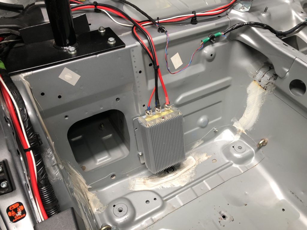
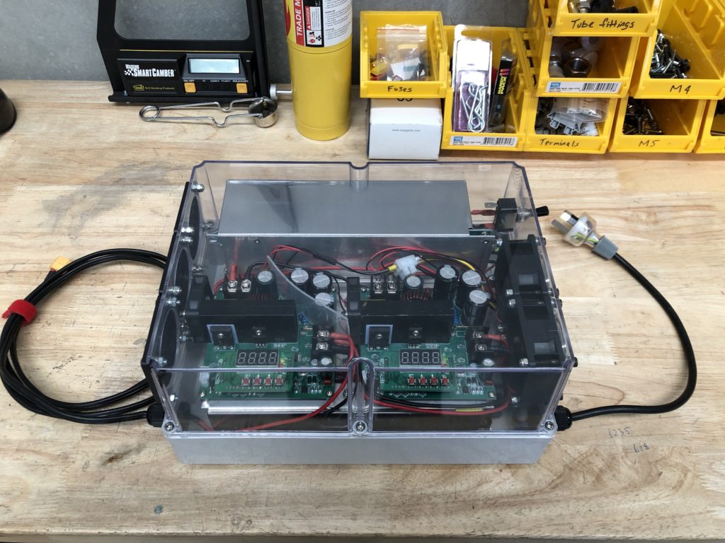
Upgrade has been completed of the onboard 12V to 48V DCDC converter to 15A unit (previously 8A unit). This allows the system Lipo battery charging current from the alternator (when the engine is running) to increase from 6A to 12A.
12V to 48V DCDC converter 15A
An external charger that uses 240VAC mains power has been upgraded from 10A to 20A charge current. This external charger eliminates the need to idle the car for long periods in between runs at motorsport events. Most events we run at have mains power available but for those that don’t a 2kVA petrol generator is used instead.
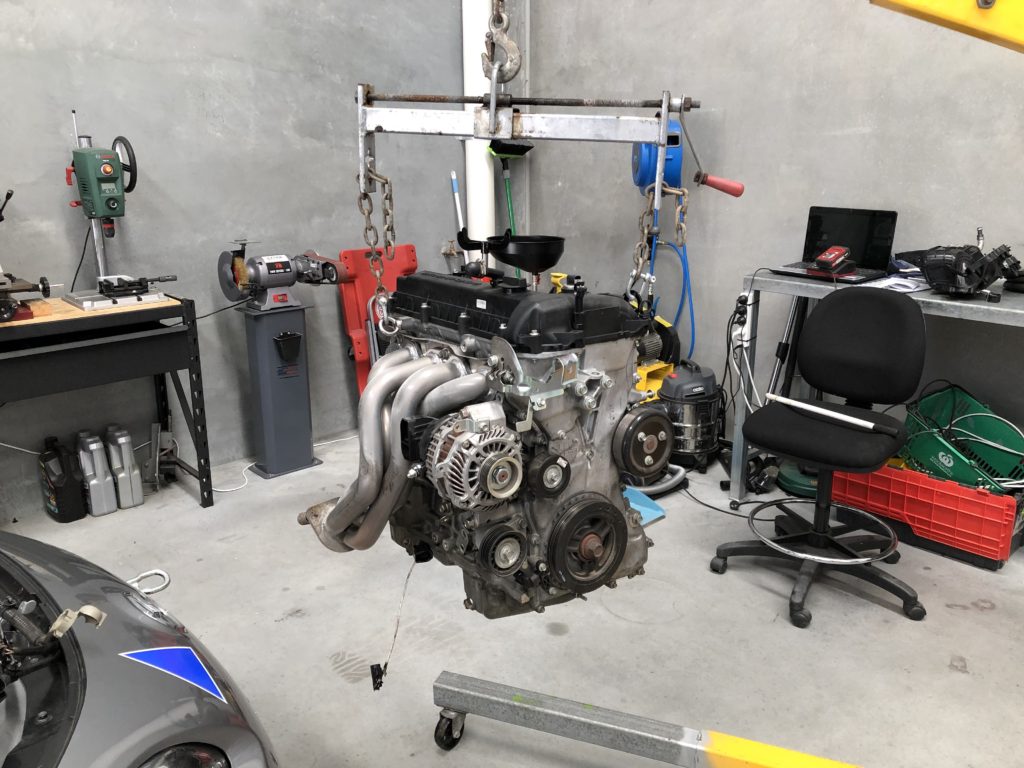
So recently had a catastrophic engine failure on track. This was my first time at a new track (Collie Motorplex) which is a longer track than where I usually run with long periods of wide-open throttle. We were running 5 lap sessions (1 warm up, 3 hot, 1 cooldown). The failure occurred right at the end of the 3rd hot lap on the 2nd session of the day. Engine was at 7500 rpm in third gear when it let go.
Managed to get of the track before I dropped any oil and ruined someone else’s day. Nothing to do other than get the motor out and try and determine the root cause of the failure.
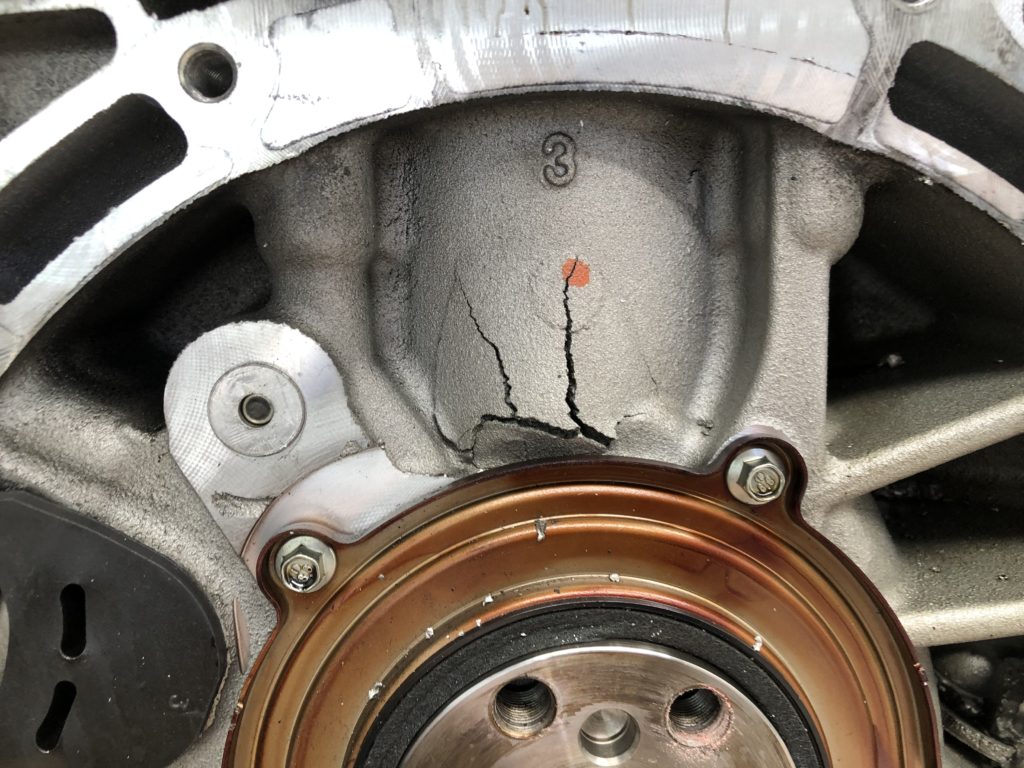
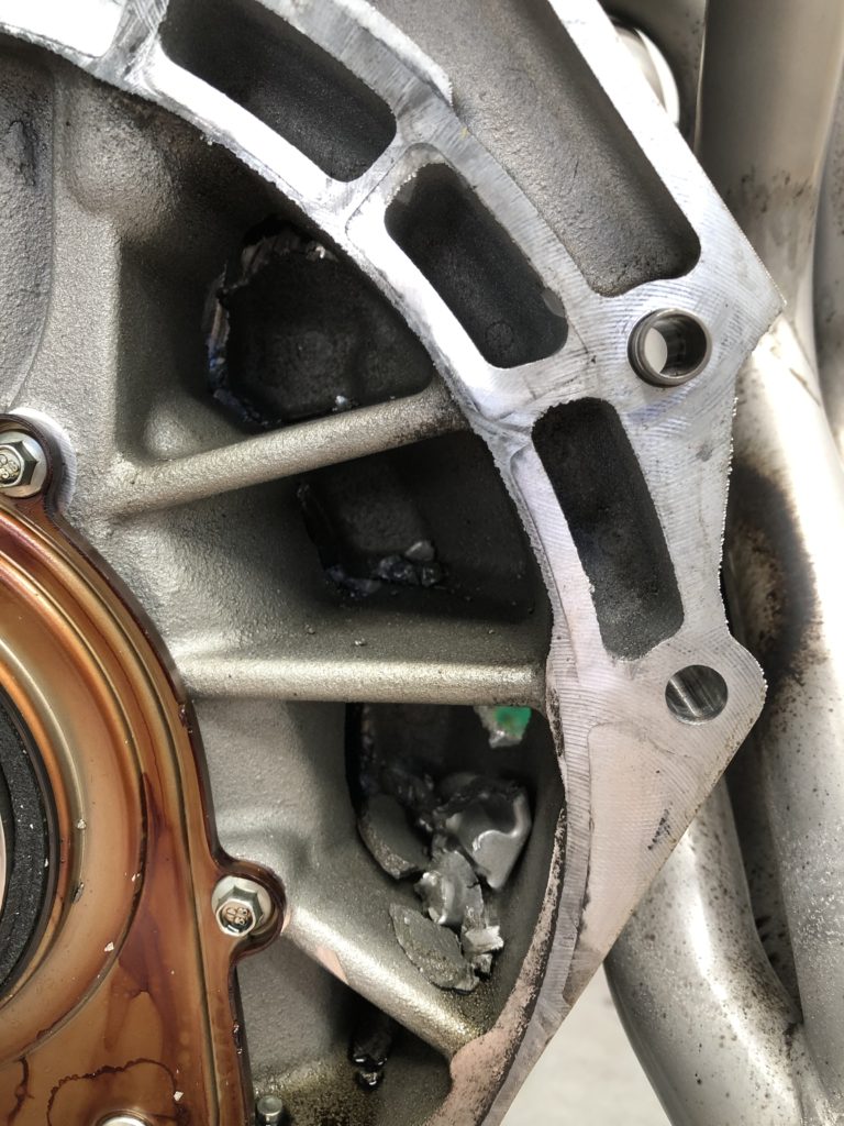
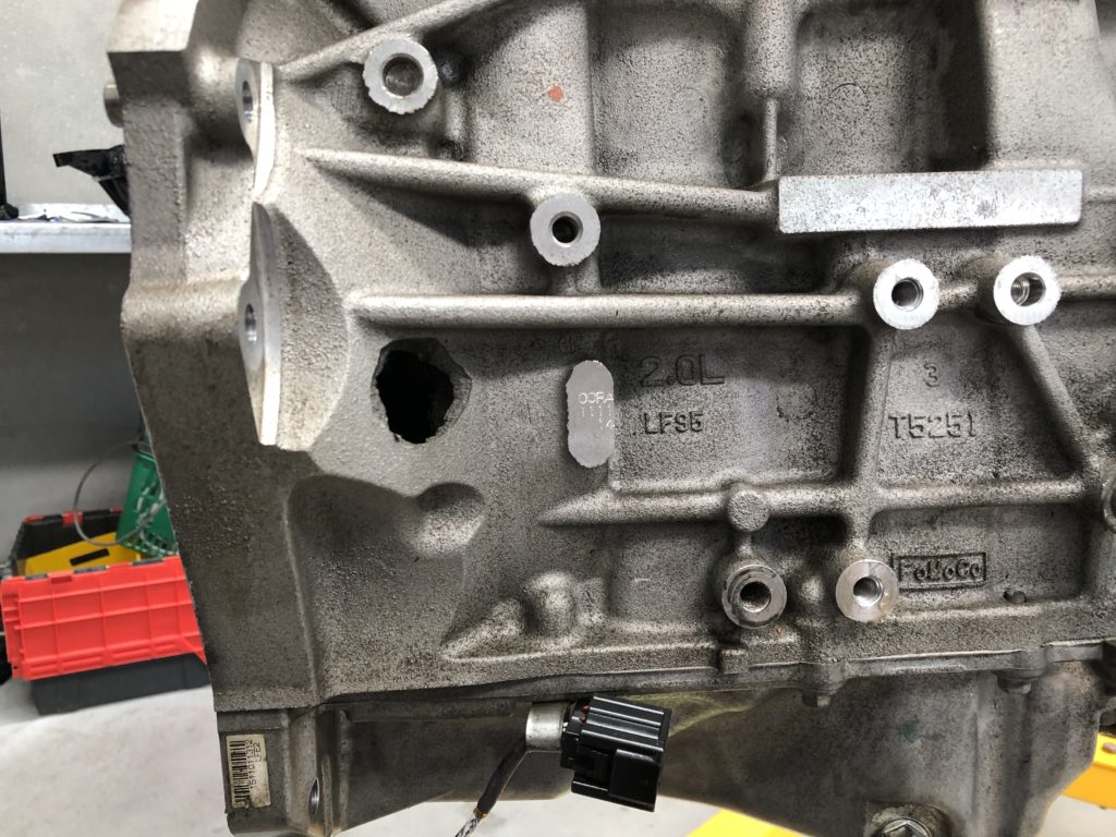
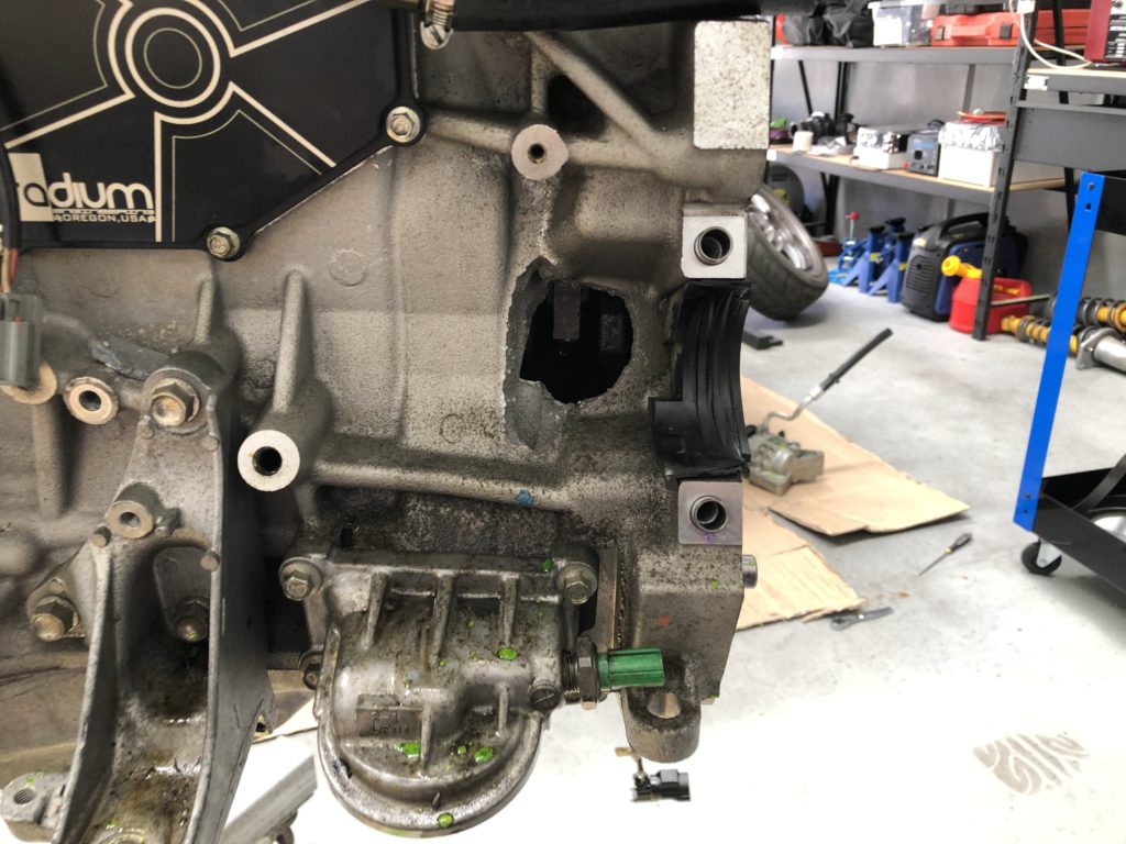
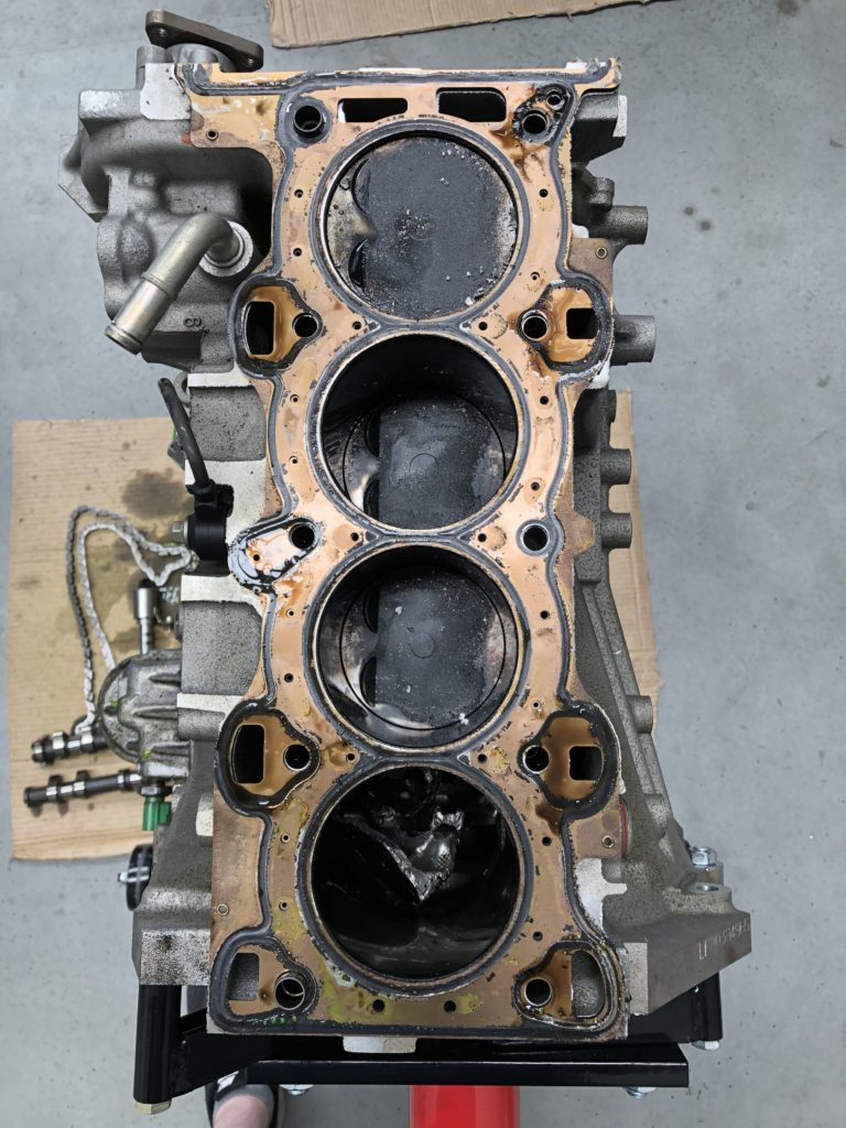
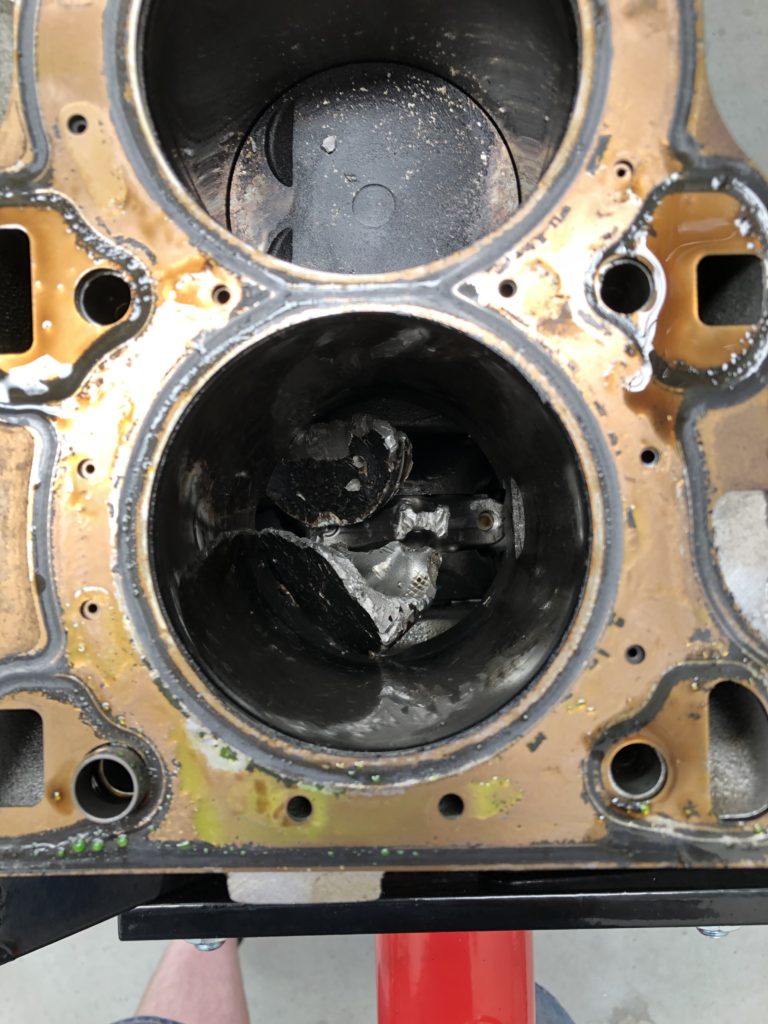
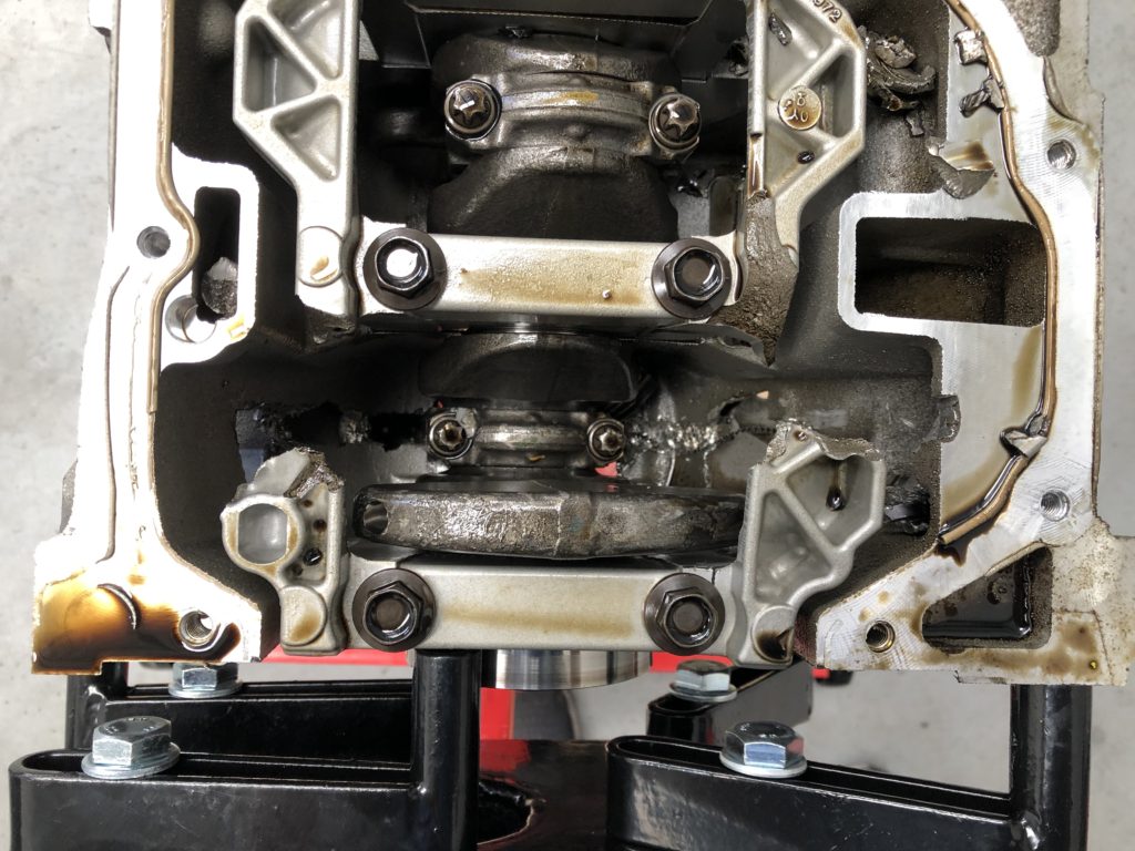
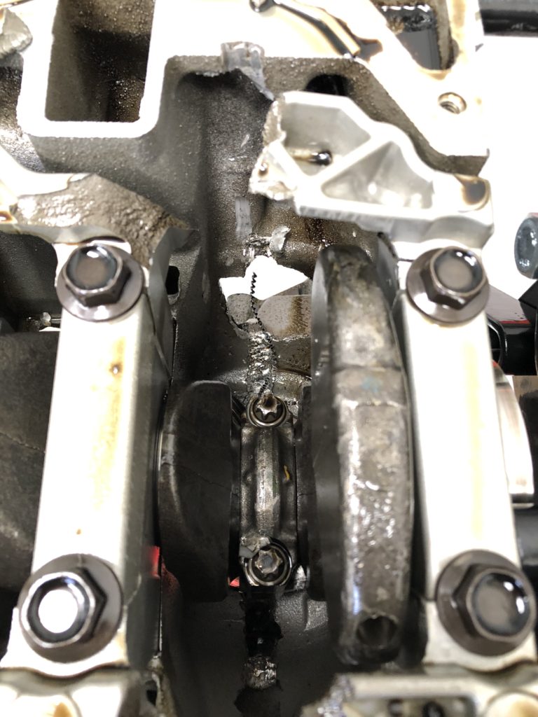
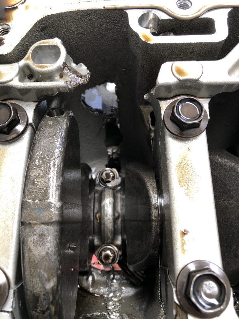
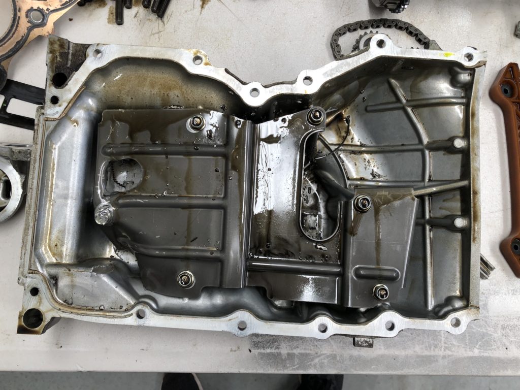
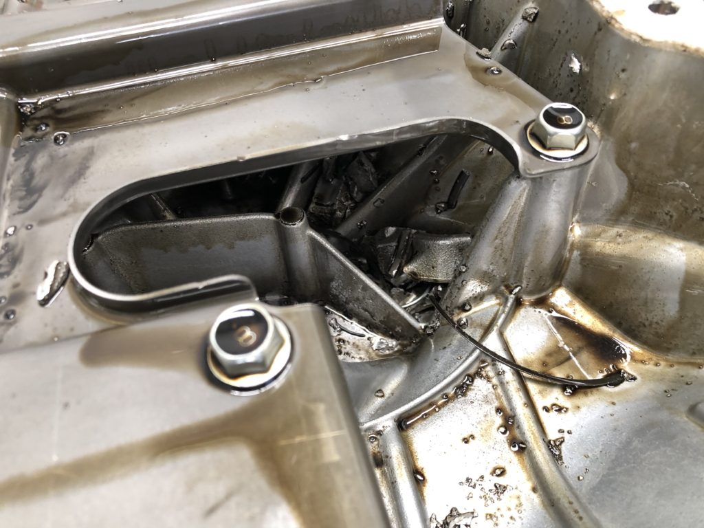
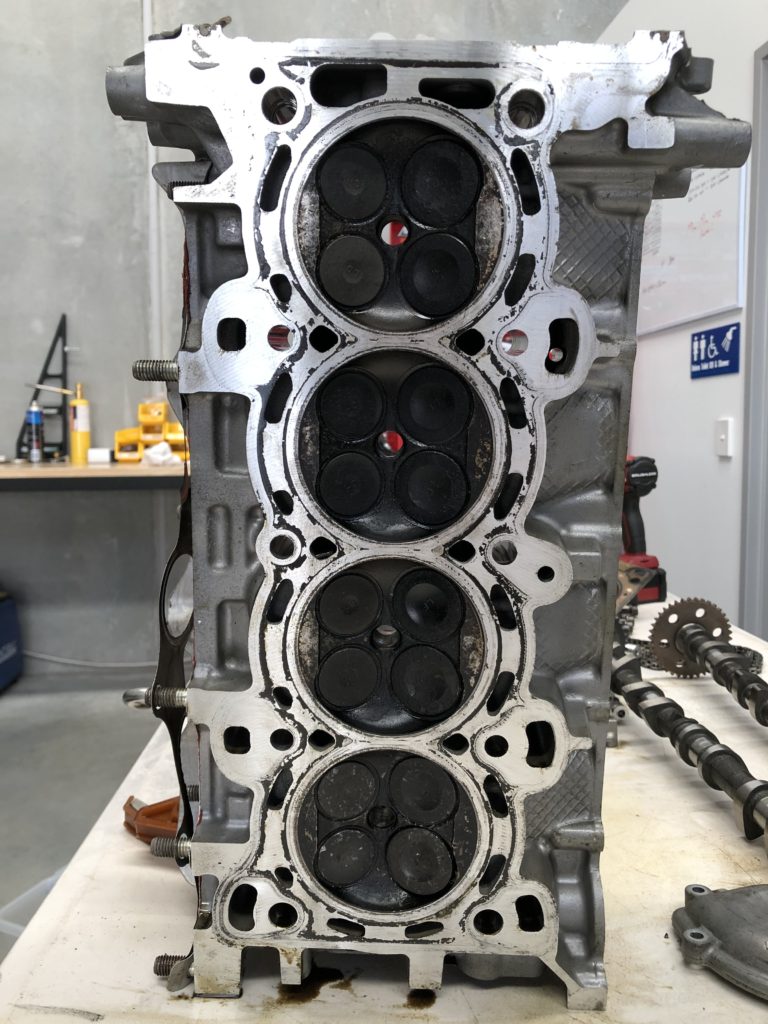
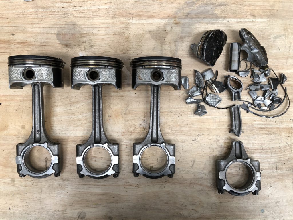
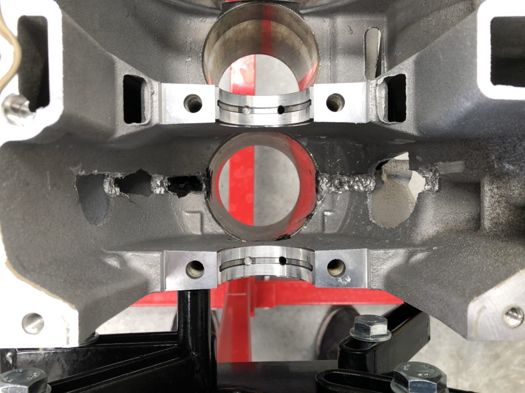
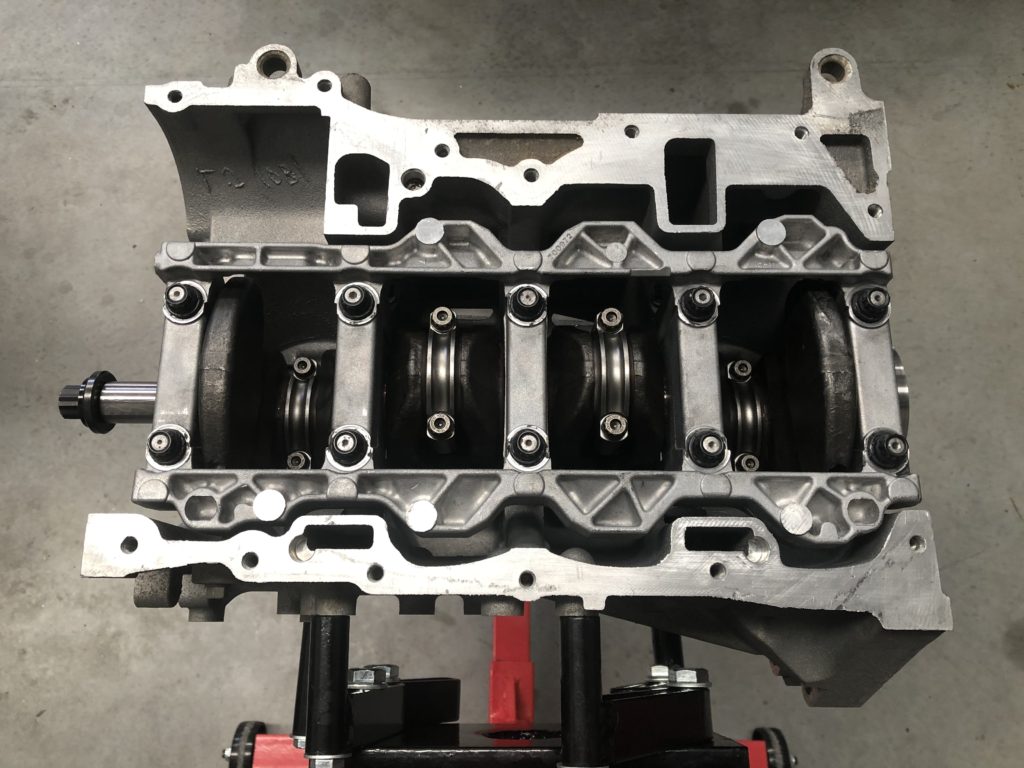
The failure occurred on cylinder 4. There are holes punched in both sides and the rear of the block. Head is relatively unscathed but cylinder 4 has bent valves. No spun bearings, crank journals and bearings look perfect so no lubrication issue. OEM pistons and connecting rods are the known weak link in these engines. Hard to tell if the rod or the piston failed first but the end result is the same.
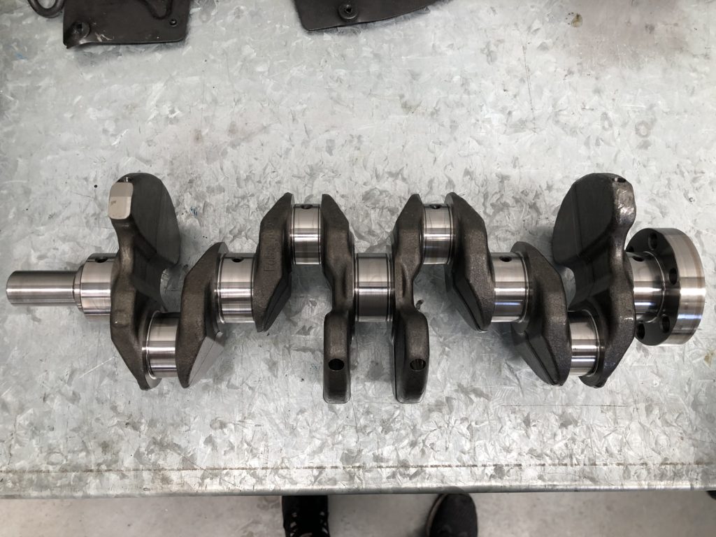
Engine outDamage cylinder 4 on rear of blockDamage on rear of blockHole in block right hand sideHole in block left hand sideCylinder head removedCylinder 4Cylinder 4Main bearing girdle destroyedSumpShrapnel in sumpHead is serviceablePistons and rodsWill have to find a replacement blockCrank looks serviceable, just some superficial marking on the rear counterweight. Will be sent for testing
I will be staying with the 2.0 MZR engine for the rebuild. It is a very popular conversion to put the 2.5 MZR engine in the NC MX-5. The problem with this for me is most of the increase in capacity of the 2.5 is from an increase in stroke. MZR (Duratec) 2.0 bore x stoke = 87.5mm x 83.1mm MZR (Duratec) 2.5 bore x stoke = 89.0mm x 100.0mm
In naturally aspirated form this makes sense as the increase in displacement and stroke gives a substantial increase in low and mid-range torque. The problem is that you cannot rev the 2.5 as high as the 2.0. I love RPM and with the electric supercharger low and mid-range torque is not an issue. The plan is to build a 2.0 with forged internals and up boost to 11psi and spin the engine to 8000rpm.
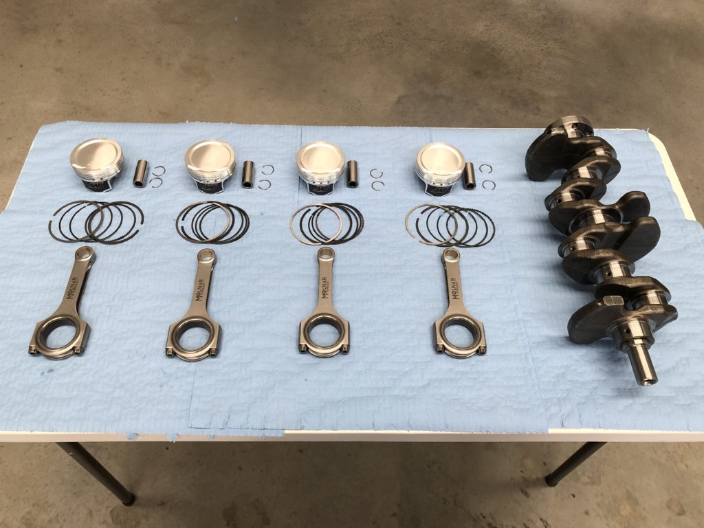
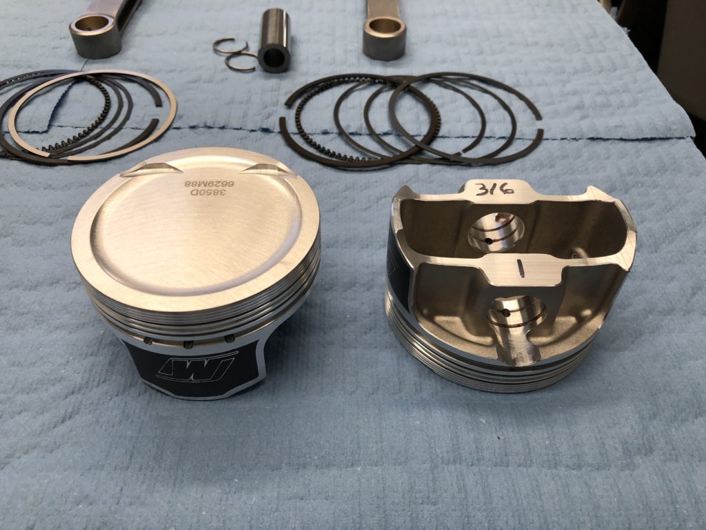
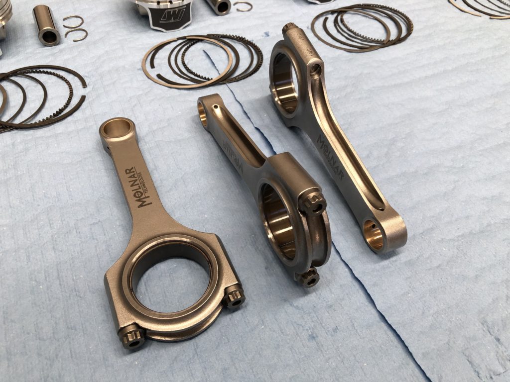
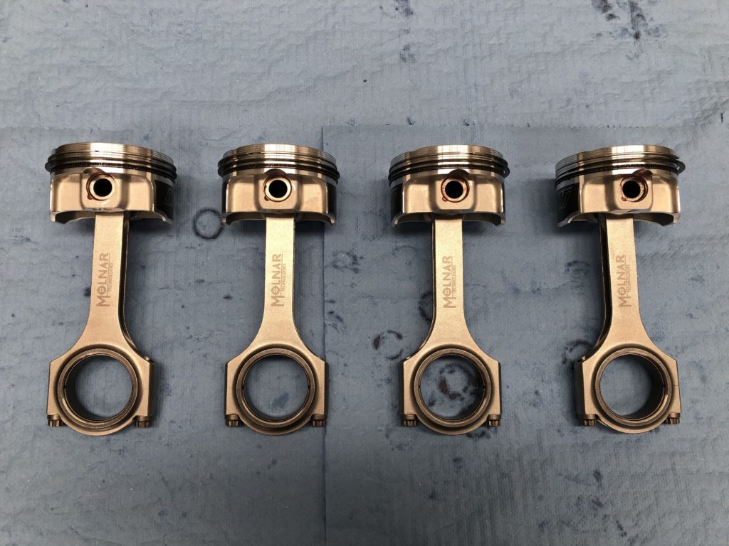
Build parts list: • Pistons – Wiseco forged 2618 alloy 88mm • Rods – Molnar forged 4340 steel h-beam with ARP2000 bolts • Main bearings – King Racing • Big end bearings – ACL Race Series • Oil system – Raceline dry sump with Peterson 1.5 gallon oil tank • Head gasket – Cometic MLS • Main studs – ARP • Head studs – ARP • Front pulley bolt – ARP • Cam sprocket bolts – ARP • Cams – Xero Limit stage 1.5 • Valve Springs – Kelford Cams KVS17 Beehive • All other gaskets and seals are Mazda OEM
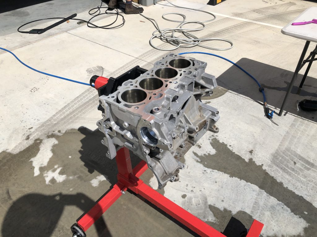
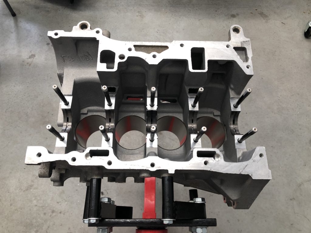
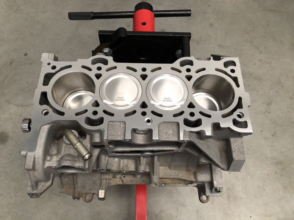
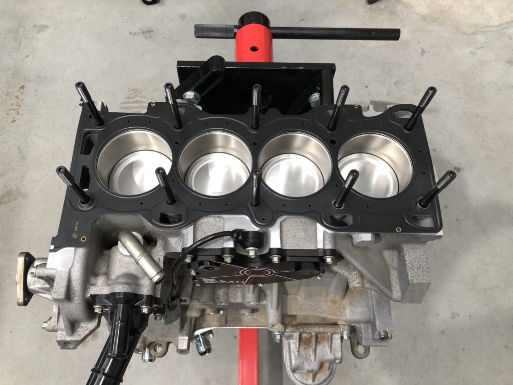
The forged 2.0 NC2 crank from the blown motor was taken to the shop for run out and crack testing. The crank tested ok so next a replacement MZR 2.0 engine was sourced and stripped for the block. Block was given to machine shop to be cleaned, bored and honed to 88mm, and decked.
Machined block having final pre-assembly clean
After some consideration I decided to open up the engine clearance from the very tight OEM specs. Main bearing oil clearance set at 1.5 thou, big-end oil clearance set to 2.5 thou, piston to wall clearance set to 3.5 thou, and ring gap set to Wiseco’s “Circle Track” spec. All other specs as per OEM. Rotating assemble was balanced at machine shop.
Balanced rotating assembleWiseco forged pistonMolnar forged h-beam rods and ACL race big-end bearingsAssembled piston and rodsPrepared block with King bearings and ARP main studs installedMain and big-end caps installed and torquedComplete short block
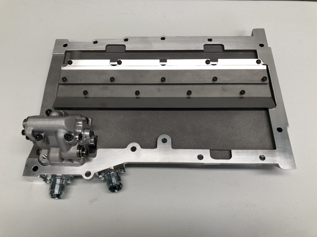
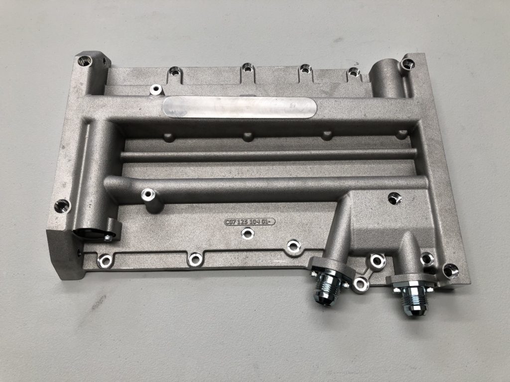
For the lubrication system I decided to upgrade the OEM wet sump system to the Raceline dry sump setup. This is a trick piece of engineering. It uses a single stage scavenge and single stage pressure pump which resides in the OEM location and uses the OEM chain drive so there is no external pumps, belts, etc. All that is needed is a external oil tank. This sump has a very low profile and the ARP main stud nuts extend further down than the factory main bolts and fouled on the sump. Some notches had to be cut into the windage trays to make it fit.
Raceline dry sump system topviewRaceline dry sump bottom view
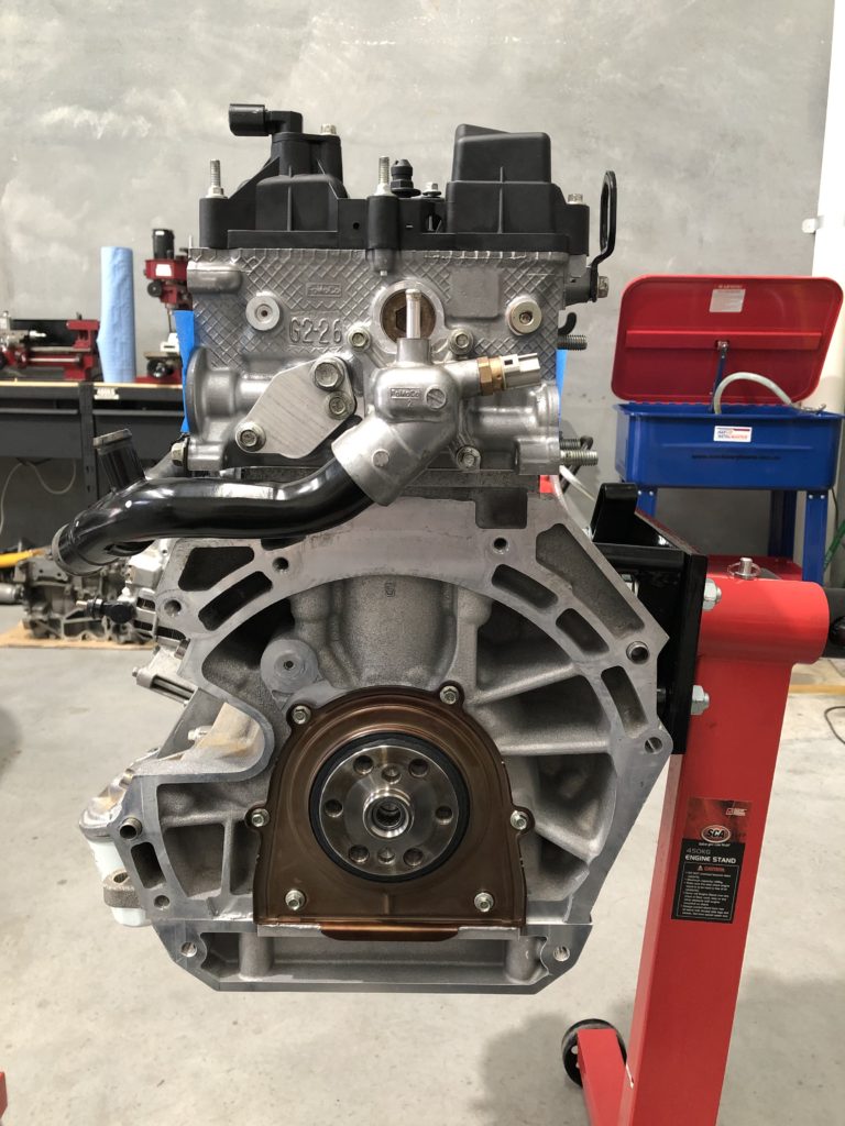
The front shaft of the crank has had a 1/8″ keyway cut into it along with the oil pump / cam timing sprocket and the front pulley. This is a insurance policy against any issues with the OEM friction retention setup.
Oil pump chain drive
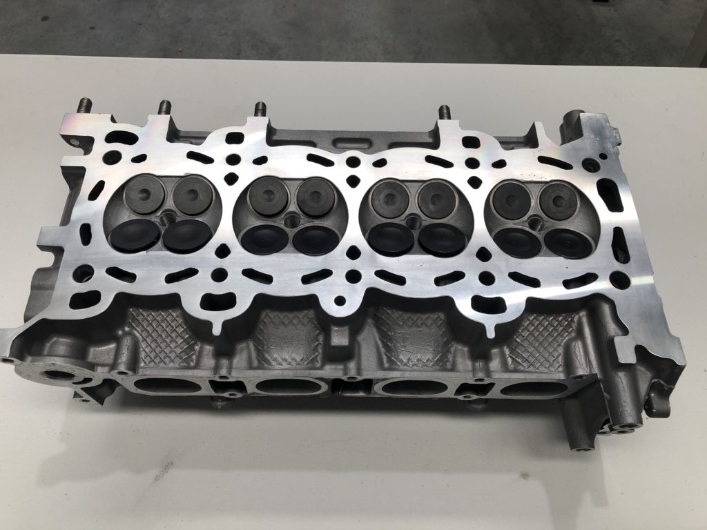
The cylinder head was given to the machine shop for a full recondition. All four valves on cylinder 4 were replaced with new items. All valve stem seals were replaced and valves seats recut. Upgraded cams and valve springs were installed, bucket tappets re-shimmed, and head was faced.
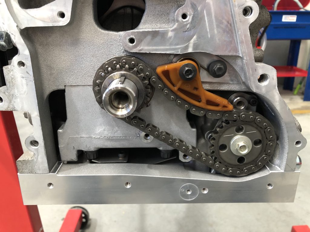
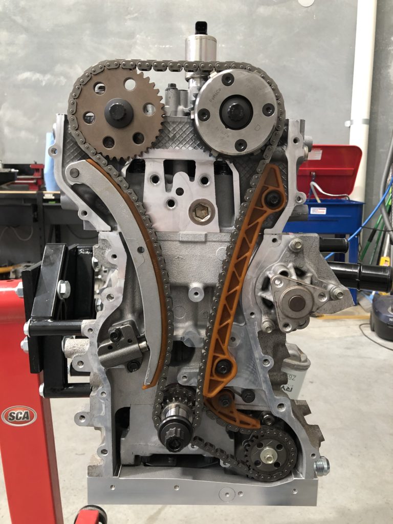
Reconditioned headARP head studs and Cometic MLS head gasketHead torqued to block and cams installedCam timing chain, guide and tensionerComplete engine front view
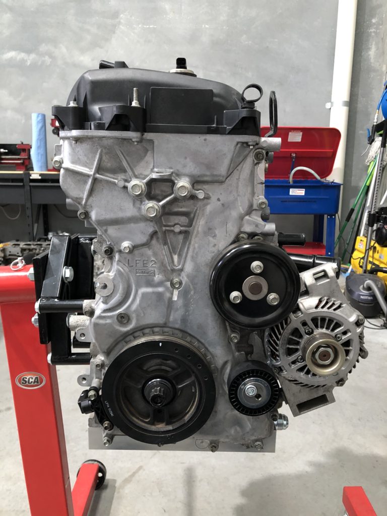
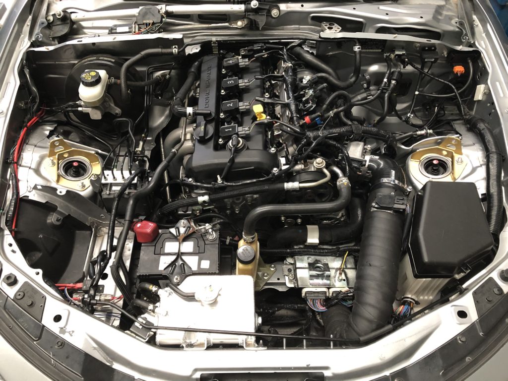
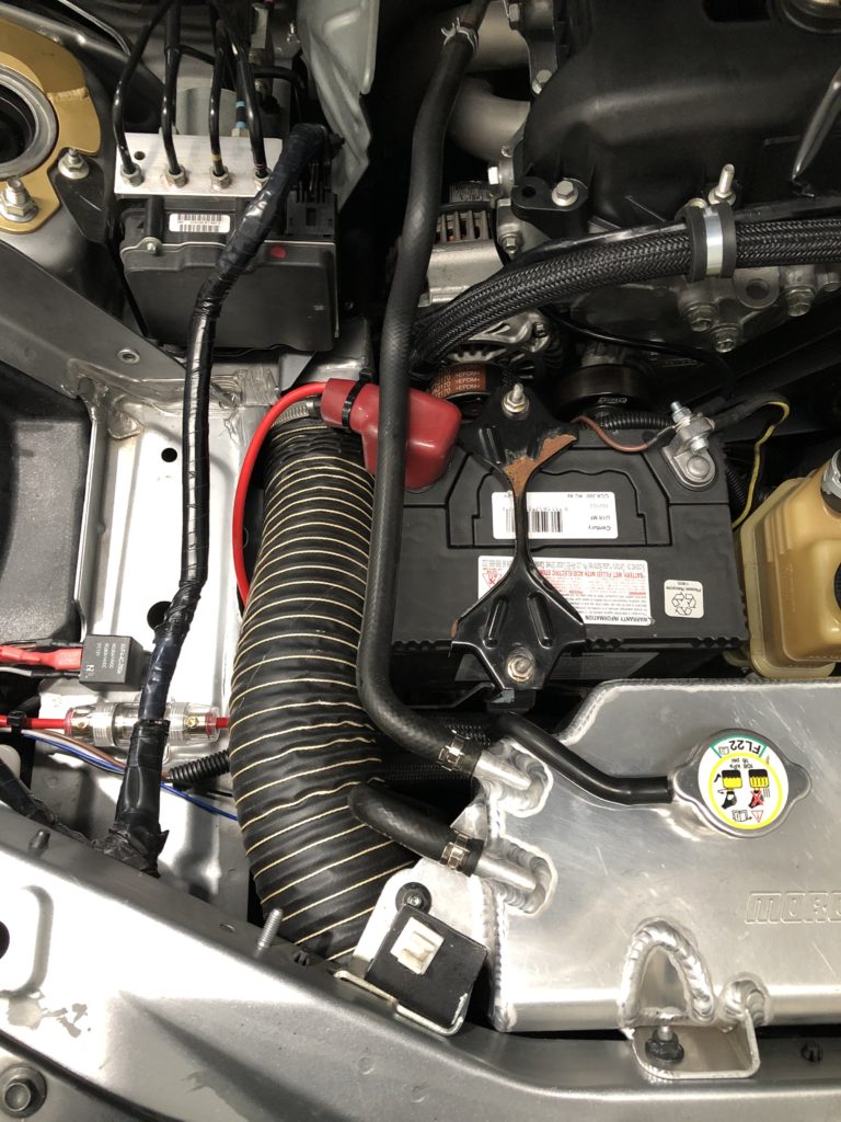
The air conditioning compressor has been deleted. This has allowed the alternator to be relocated to the other side of the motor to get it away from the hot exhaust manifold. The replacement alternator was sourced from a Mazda 3.
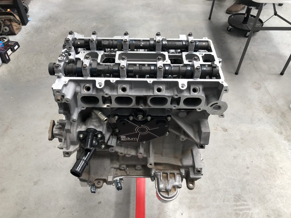
Complete engine side view
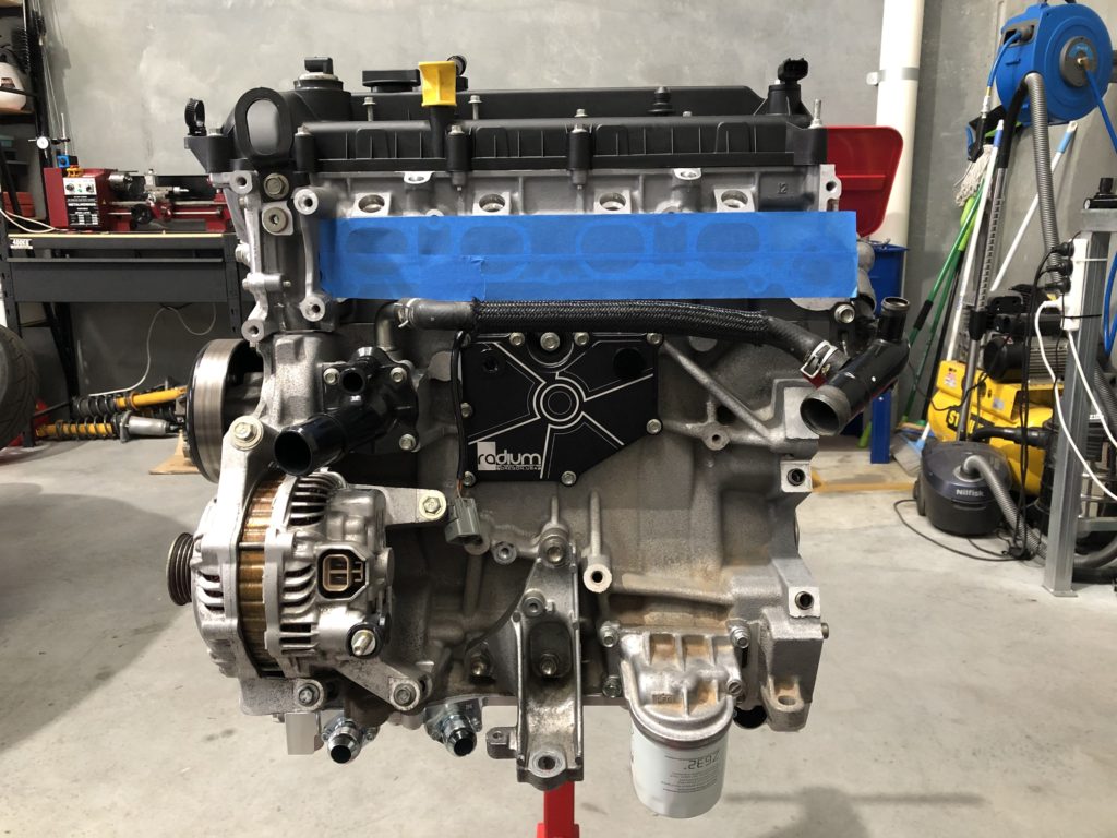
The factory oil separator and crankcase ventilation valve have been blanked off. The crankcase will breather out of the cylinder head cover into a catch can oil separator.
Complete engine rear view
The exhaust gas recirculation valve has been deleted and blanked off on rear of cylinder head.
With the motor complete it was test fitted to engine bay to determine location of dry sump oil tank and routing of oil lines. The engine bay is too crowded to house the the oil tank so it will live in the passenger seat footwell. It also became evident that routing of oil lines would not be easy due to the charge pipe for the supercharger running down the left hand side of the motor.
Dry sump oil line and charge pipe clash
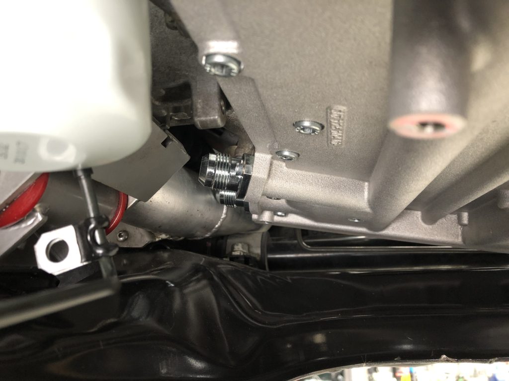
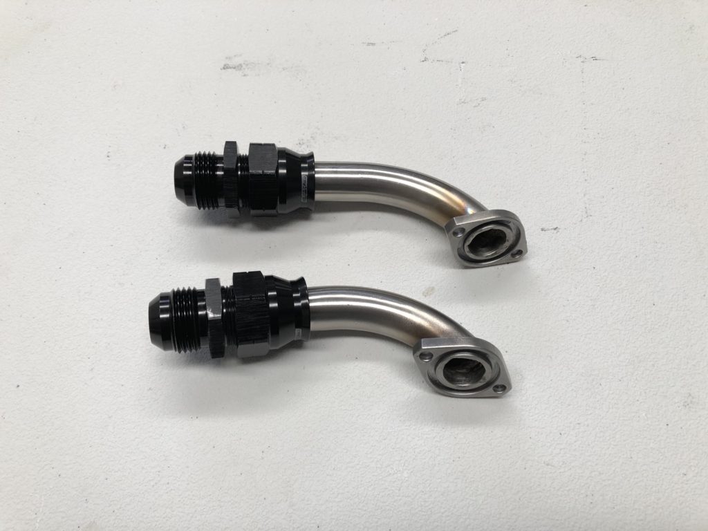
Even the tightest radius AN fitting would not clear and there is no other path the charge pipe can take. To solve this problem we decided to make tight radius 90 degree hard lines to connect directly to the sump then change from hard line to hose. The flange was cut off the AN fittings supplied with the Raceline sump and 3/4 inch 316 stainless steel tube was welded to the flanges.
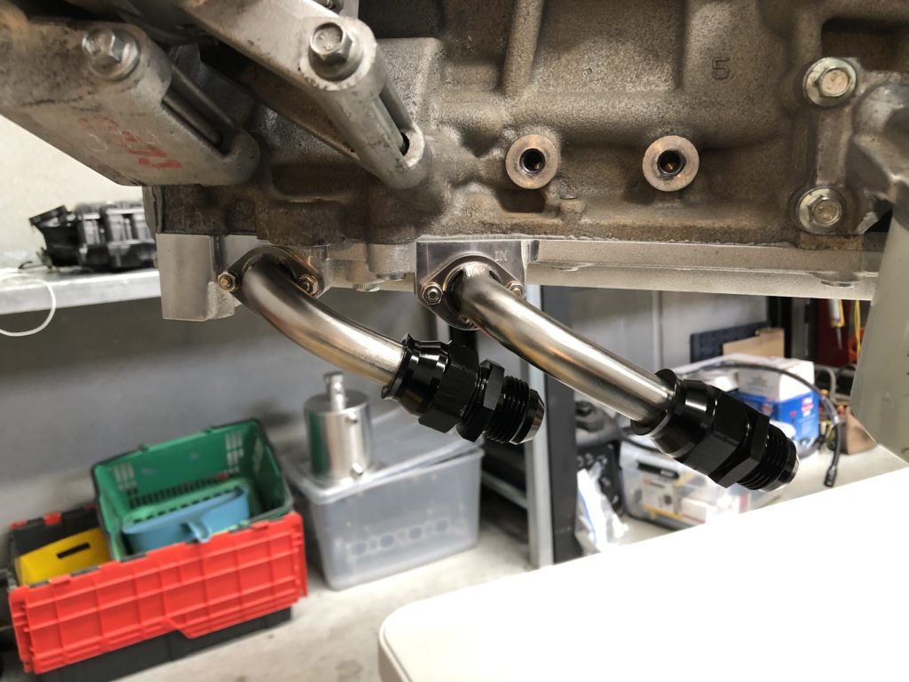
Hard line fittings for dry sump connectionHard line fitted to sump
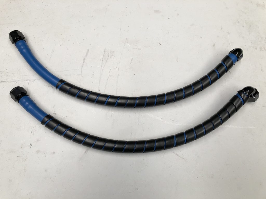
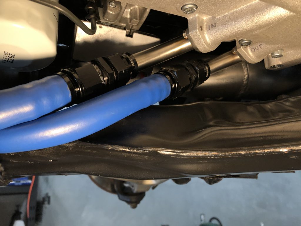
The original plan was to use stainless steel braided PTFE hose for all oil lines. A problem was encountered as this hose wants to kink with anything more than a slight bending radius. The path to get from the sump to the firewall is tight so for this section we changed to high temp (150 degC) AN12 Parker PKR rubber push-lok hose.
High temp rubber hose linesHoses connected to hard linesHose route avoids charge pipe and maintain serviceability of oil filter
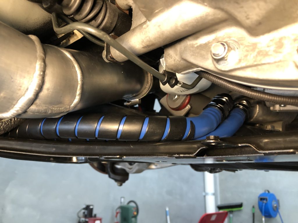
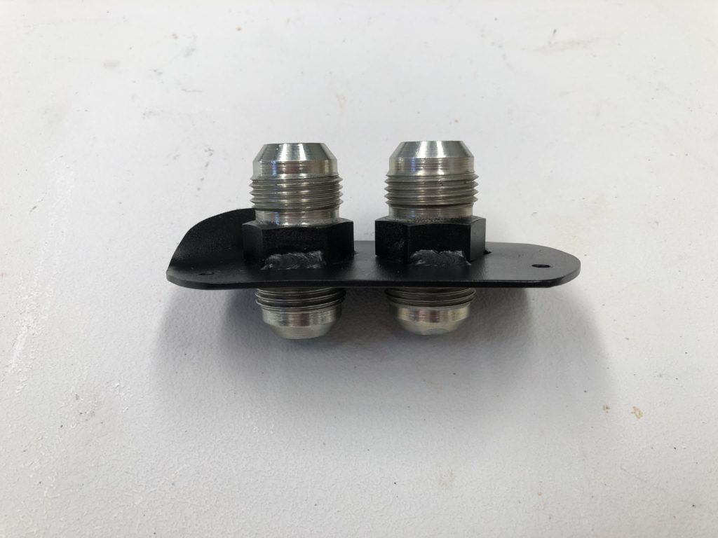
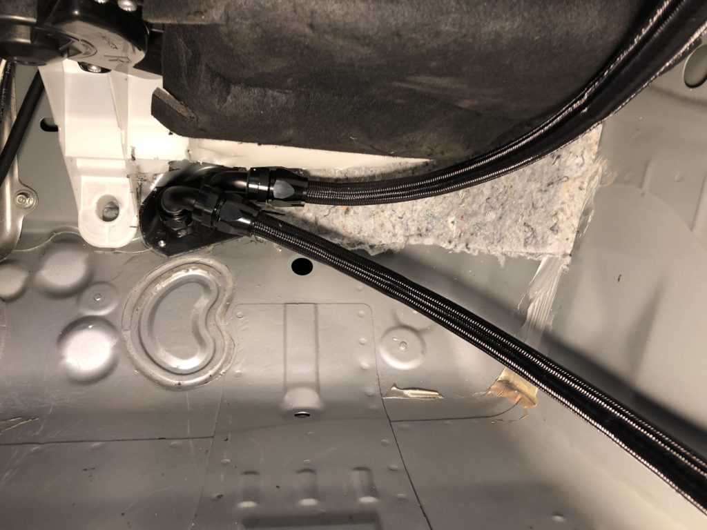
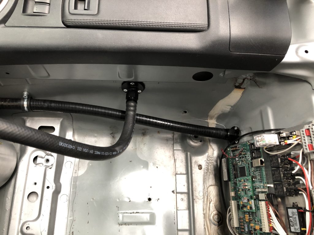
The hoses transits through the firewall from the left front wheel well into the passenger foot well. A bulkhead fitting was fabricated out of two AN12 unions.
AN12 bulkhead fittingFirewall transit external
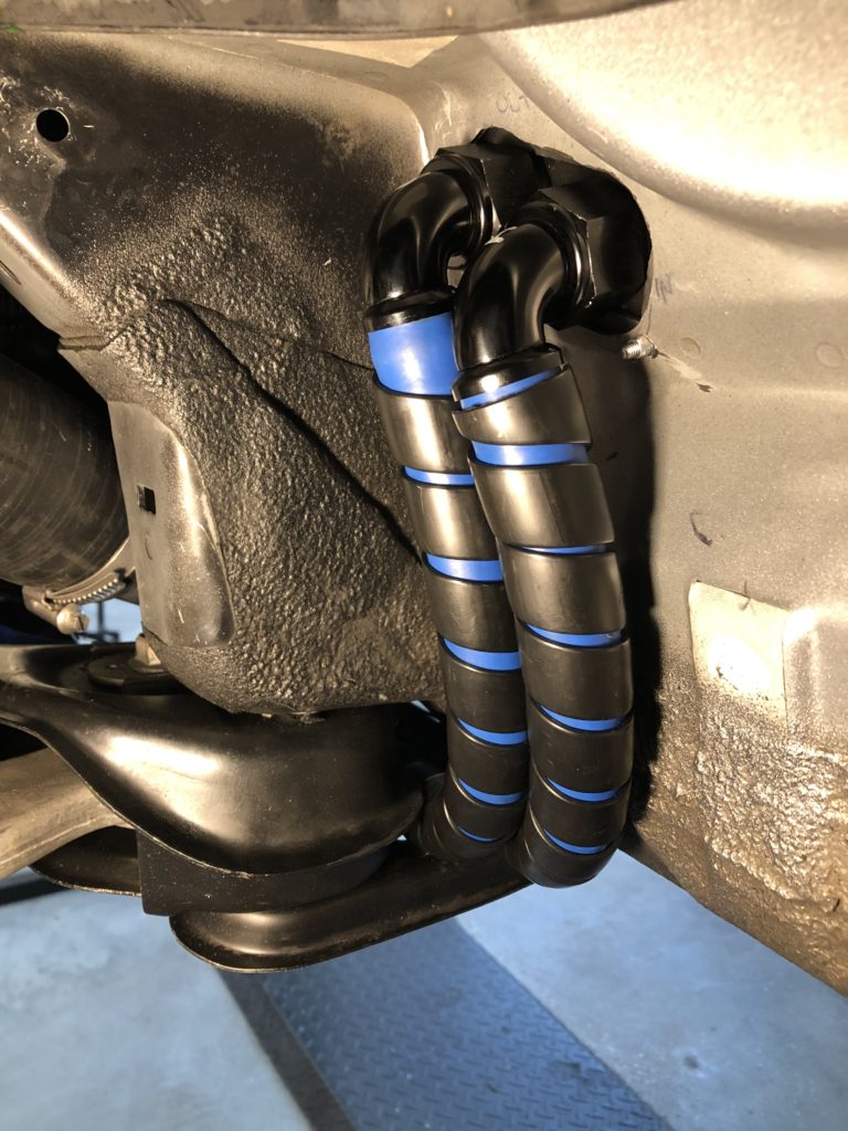
Stainless steel braided PTFE AN12 hose was used for oil lines inside the vehicle.
Firewall transit internal
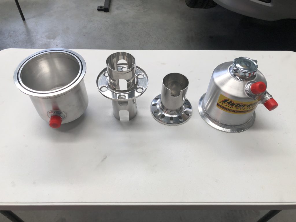
For the oil tank a Peterson 1.5 gallon tank was selected. The tank has internal baffling for the deaeration of the scavenge oil and maintains a tall column of oil over the pickup. It can be split in two with the two halves held together with a v-clamp.
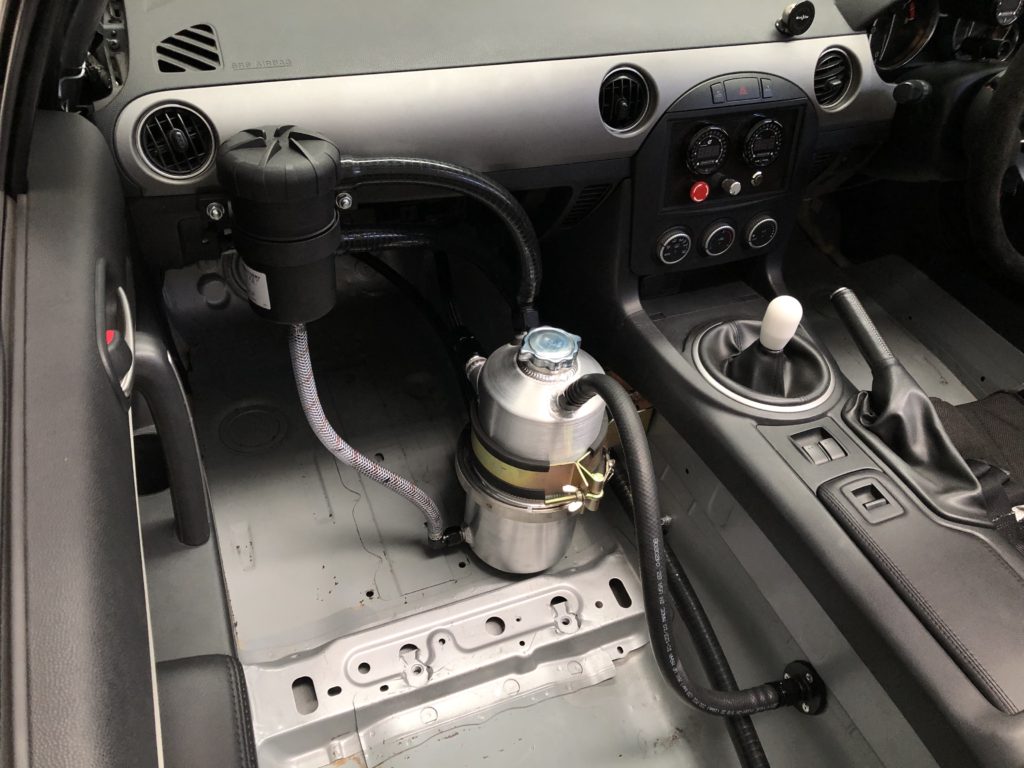
Peterson 1.5 gallon tank Oil tank internal bafflesOil tank mounted in vehicle
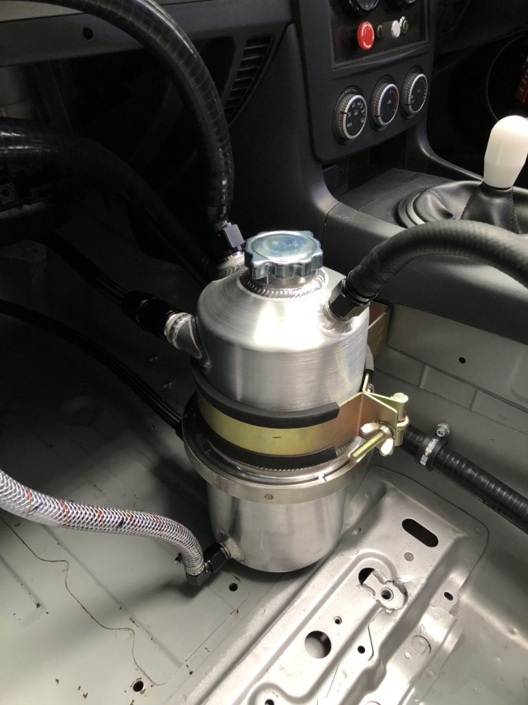
A additional AN8 and AN10 male fitting were welded to the oil tank for the breather system. The engine breathes out of the head into the top of the oil tank. The oil tank breathes into a Mann & Hummel Provent 200 air/oil separator. Any oil that accumulates in the separator is returned to the tank via a clear 1/2″ hose that doubles as a tank level sight gauge.
Provent 200 air/oil separator top leftBreather from engine through transmission tunnel, outlet of air/oil separator to rear of vehicle
Finally the wiring harness was reconnected to the engine along with fuel, coolant, and vacuum lines. All fluids were filled. For initial break in a quality SAE 30 mineral oil was used with half a bottle of Red Line break-in additive to add some ZDDP to the mix. Engine was cranked with injectors isolated and spark plugs removed to prime oil pump. Spark plugs were installed and engine fired first crank and was run at approx. 2500 rpm for 20 minutes to break in the cams. Next it was taken out on the road and over 150 km of driving the load, rpm, and boost were gradually increased to bed in the piston rings.
Engine install complete
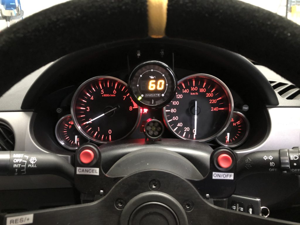
Following the break-in the oil was dropped and the oil filter was cut open to inspect filter medium with no surprises found. Oil tank was refilled with Mobil 1 0w-40. To monitor oil pressure and temperature on the new motor a Innovate Motorsport MTX-D dual function gauge was installed in the instrument cluster. With engine at operating oil temp, oil pressure is 30 psi at idle, and 60 psi from 3000 rpm to redline.
The built engine is running well but the addition of the oil temperature gauge has been educational. When on boost the engine oil gets very hot (north of 120 degC) very quickly. Decided not to run the new engine on track until an oil cooler was installed.
After accessing the options, an oil to water (coolant) heat exchanger was selected over an oil to air cooler due to:
Simpler installation – an oil to water heat exchanger can be mounted closer to the engine to minimise length of oil lines. Also, there are already two radiators at the front of the car so mounting an oil to air cooler would be difficult
Due to coolant being at 85-90 degC an oil thermostat is not required
On a cold start the heat exchanger has the added benefit of heating the oil to bring it up to operating temperature quicker. Engine oil takes a lot longer than coolant to come up to temp
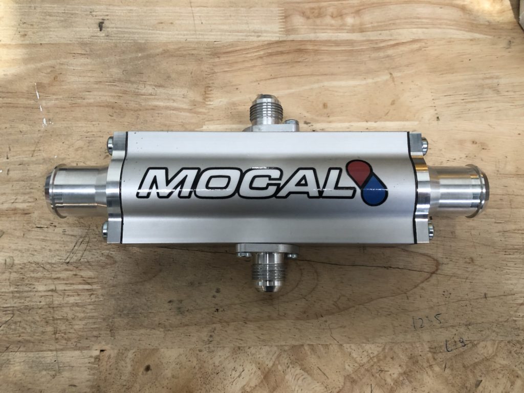
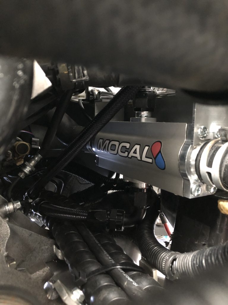
The Mocal Laminova C43 180mm core heat exchanger was selected. Mocal documentation states that the performance of the heat exchanger in cooling the engine oil is comparable to a typical 16 to 19 row oil to air 235 matrix cooler.
Mocal Laminova heat exchanger
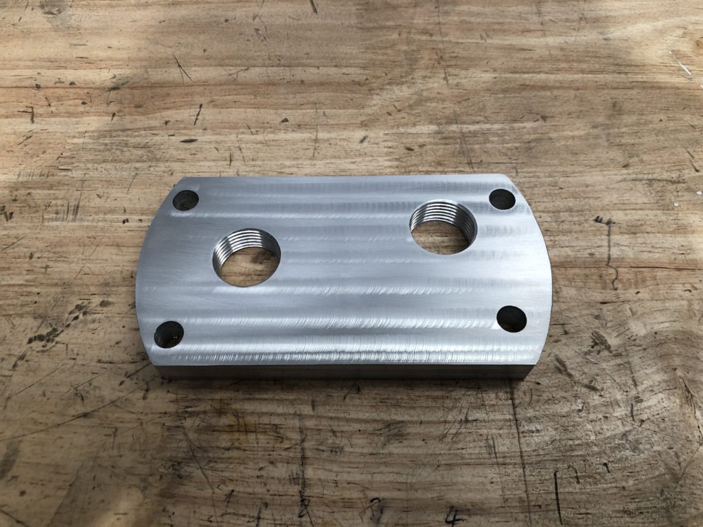
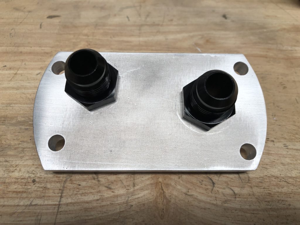
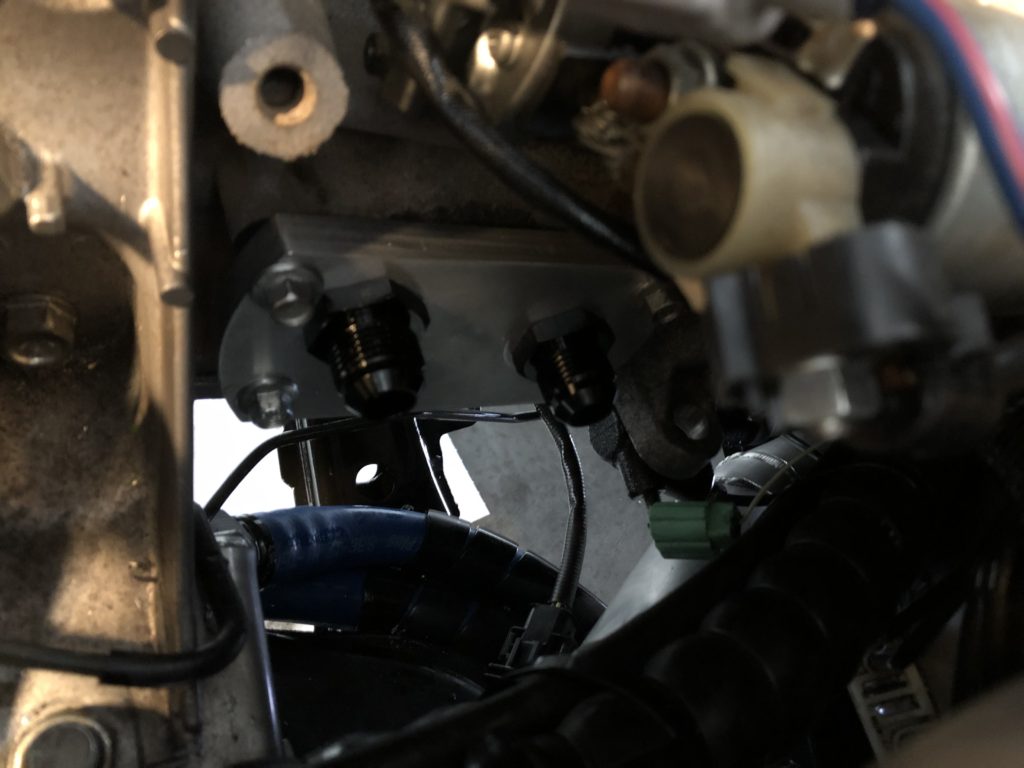
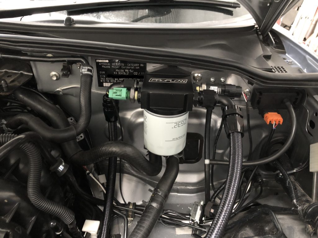
There is no room for a sandwich plate so an oil take-off plate was fabricated from 12mm aluminium plate and the oil filter was relocated using a remote oil filter mount.
Oil take-off plate Oil take-off plate with AN10 fittings installed Oil take-off plate fitted to block
The heat exchange was mounted to the left chassis rail. The hot coolant comes of the back of the head runs down the left side of the engine, through the heat exchanger, then into the radiator.
Heat exchanger mounted to left chassis rail
For the oil circuit, pressurised oil exits the block, passes through the heat exchanger, through the oil filter, and back into the block.
Remote oil filter mounted to firewall
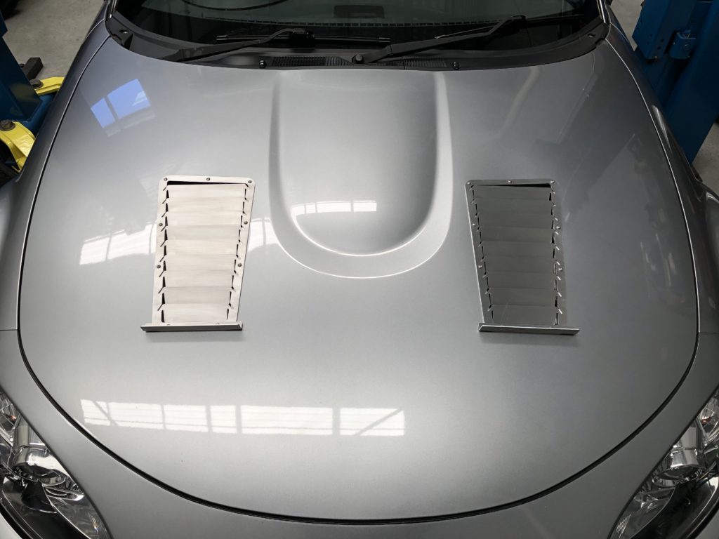
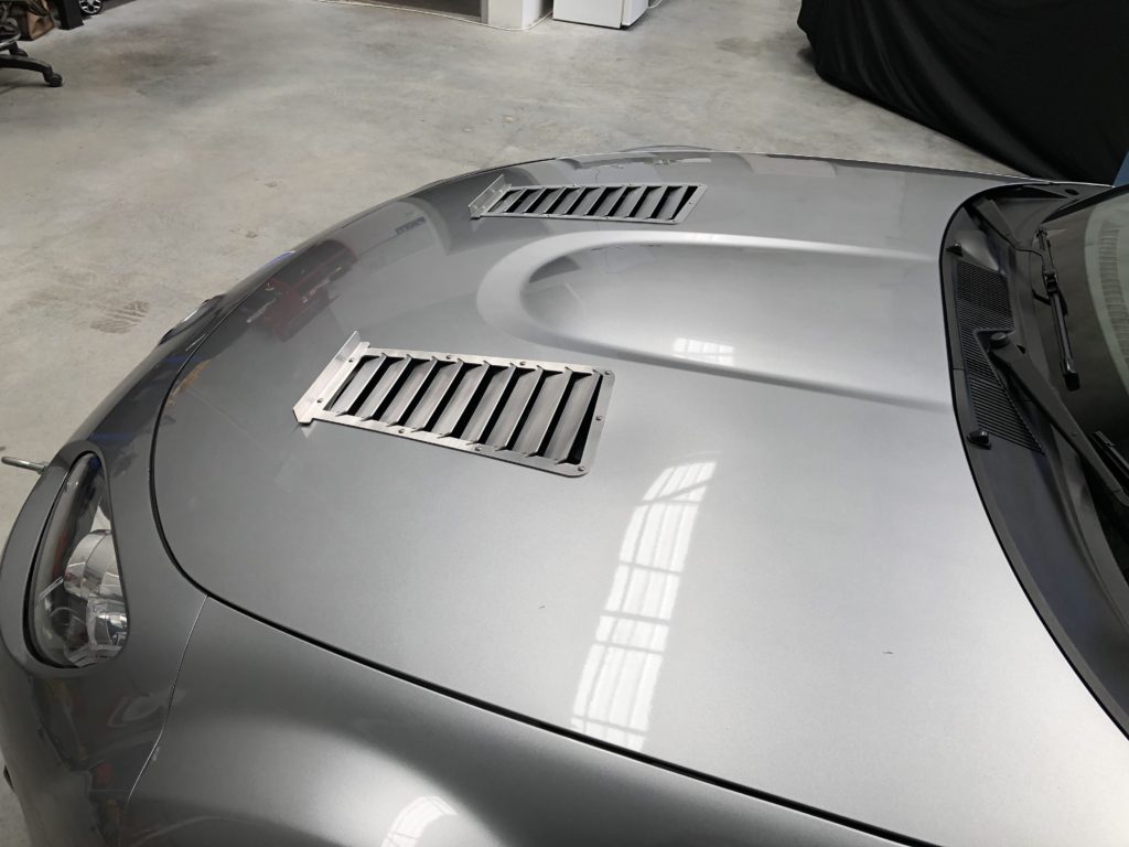
Bonnet louvers have also been installed. This will increase air flow through the radiator that now needs to deal with increase heat load of cooling the engine oil. Louvers also assist with reducing under bonnet temperatures and heat soak.
Louvers installed on factory bonnet Louvers installed on factory bonnet
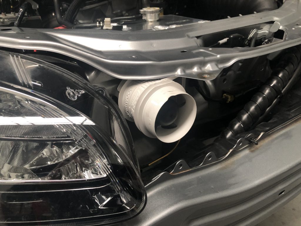
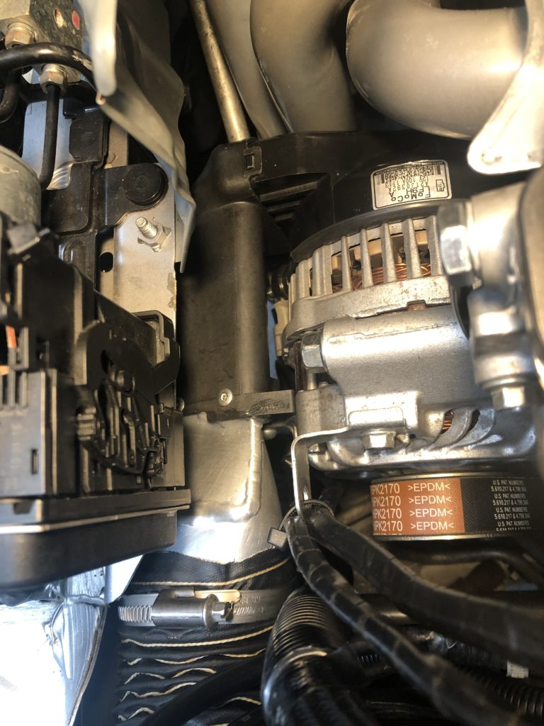
To accommodate the new oil cooler the alternator had to be moved back to the right-hand side of the engine. This wasn’t a concern as moving the radiator to the left side did not help the alternator overheating issue. A forced air-cooling system has been installed to enable the alternator to supply the electrical current required for charging the system battery when the car is stationary.
A 3” inline blower draws cool air from behind the bumper (but in front of the radiator). This blows air through a 3” SCAT tubing into some custom ducting, then into the OEM alternator shroud. This channels cool air onto the rectifier and voltage regulator on the back of the alternator which has been overheating and causing the alternator to cycle out.
3″ inline blowerSCAT tubingAlternator cooling ducting and shroud
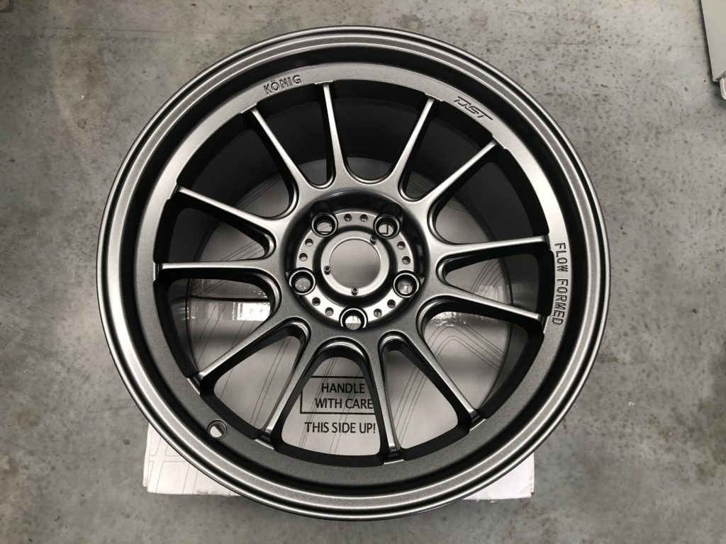
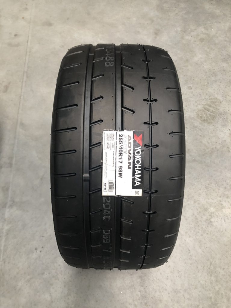
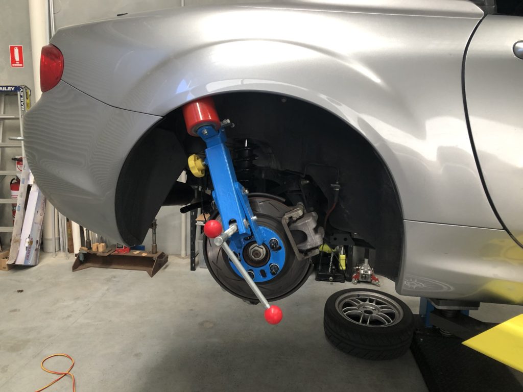
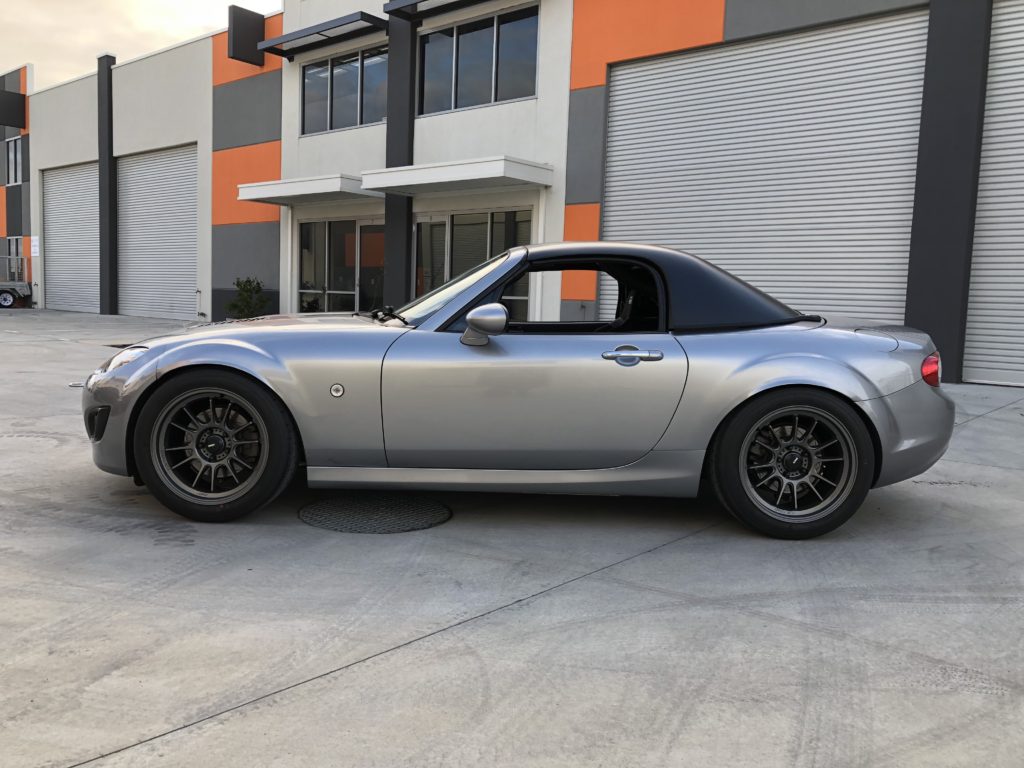
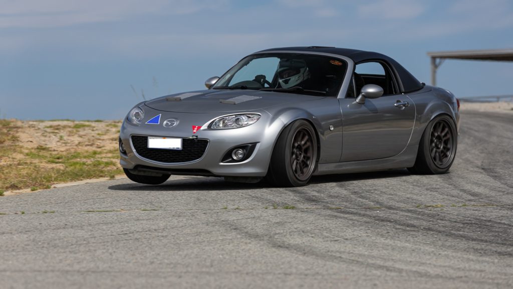
It’s time for new tyres. I have been running Enkei RPF1 17×7.5 with 215/45R17 tyres for about 4 years. I need more grip to make best use of the torque and power the car is now producing and to also be competitive in the racing class I am now running in. No point doing things by halves so ordered a set of Konig Hypergram 17×10 and 255/40R17 Yokohama A052 tyres (have heard good things about these tyres). This is as big as you can go on a NC MX-5 without running fender flares but the fenders did need quite a bit of massaging to eliminate rubbing.
Konig Hypergram 17×10Yokohama A052 tyresMessaging guards with rollerWheels and tyres mounted
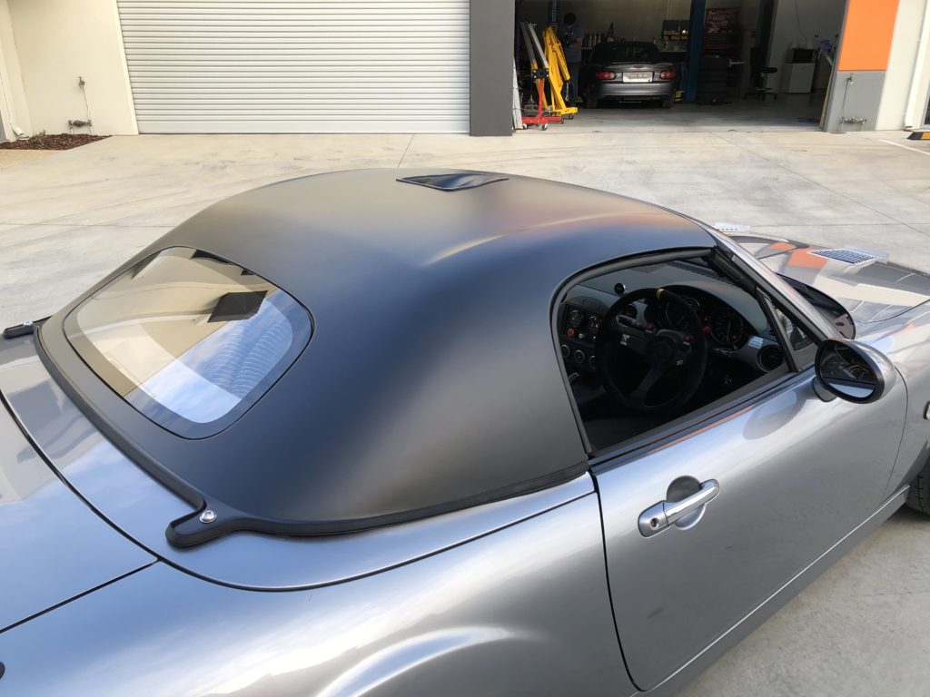
I have also ordered a light weight hardtop from David at Lightyear composite in Melbourne Australia. This is approx. 30 kg weight saving over the power retractable hardtop and will improve aero. Hardtop was painted with 2 pack satin black.
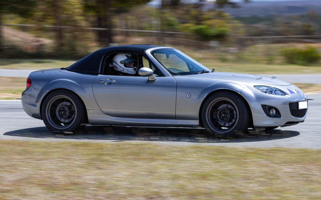
Been awhile since an update. The new built engine is running well. I have been chasing miss fires and oil leaks but everything is sorted now. Mike from Xero Limit has looked at and tweaked the tune. Engine feels strong. Still running 8psi boost and a redline of 7500 rpm. I have a big upgrade coming which will see a jump in boost pressure.
Below is a video and photos from recent event a Jack’s Hill Climb. This was a non-timed practice event organised by a friend. Grip from the new tyres is mega. I can just floor the throttle out of most corner and it just hooks up and goes. The new tyres did change the balance of the car with the car tending to oversteering on corner entry. The front sway bar was adjusted one hole stiffer and that has solved that issue. The tyres are so sticker I can’t do handbrake turns with the factory handbrake anymore. Hydraulic handbrake is on the to do list.
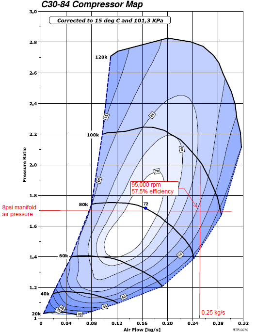
To sum up the project so far, a functional electric supercharger system has been developed in line with the original project concept. With the current setup the maximum boost pressure attainable at maximum engine load and speed is 8psi measured at the intake manifold (this equates to around 10psi at the outlet of the compressor). This is short of the 11psi goal. The main reason for this is the Rotrex C30-84 supercharger is operating too far outside of its efficiency island to increase boost pressure further. With the originally sizing the compressor, a few mistakes were made:
Underestimated volumetric efficiency of the engine which was exacerbated by upgraded cams, extractors, and 3” exhaust system
Used compressor sizing logic based on a centrifugal supercharger being driven of engine crank which is an exercise in compromise
Did not adequately allow for pressure drop across intercooler and charge pipe
Below is compressor map for the current C30-84 supercharger at the maximum operating point.
Rotrex C30-84 supercharger at the maximum operating point
The performance, and drivability of the system at only 8psi boost have exceeded expectations so investing more time and resources into optimizing the system is justified. The major upgrade will include:
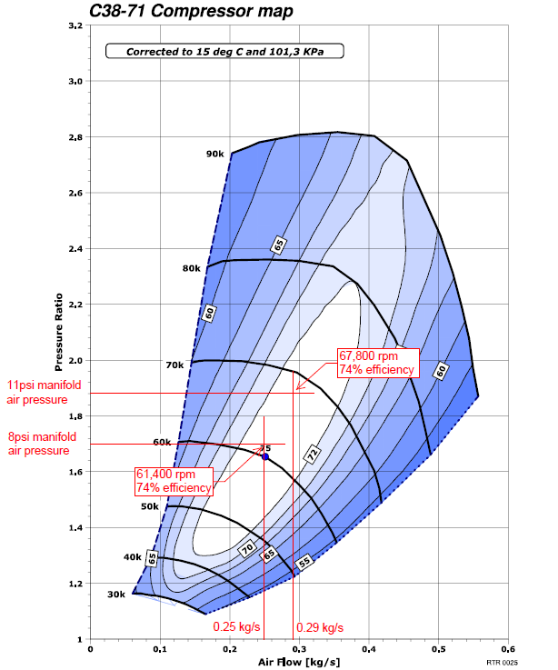
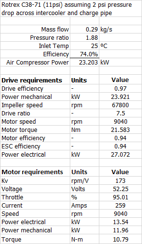
From the data collected so far, I now have a accurate mathematical model for calculating the required mechanical power, electrical power, and motor voltage/current to turn a centrifugal compressor at any combination of pressure ratio, mass air flowrate, impellor speed, and compressor adiabatic efficiency. The decision was made to size the new compressor for maximum efficiency at the maximum operating point thus maximizing the available electrical power. After modelling the Rotrex C38-71 was selected for the upgrade.
Below is the compressor map for the new C38-71 supercharger showing the 8 psi and 11 psi operating points.
Rotrex C38-71 compressor map
The only issue with sizing the compressor for peak efficiency at max boost and max mass air flow is open throttle compressor surge at lower engine speeds. If this becomes an issue, I have some plans to mitigate.
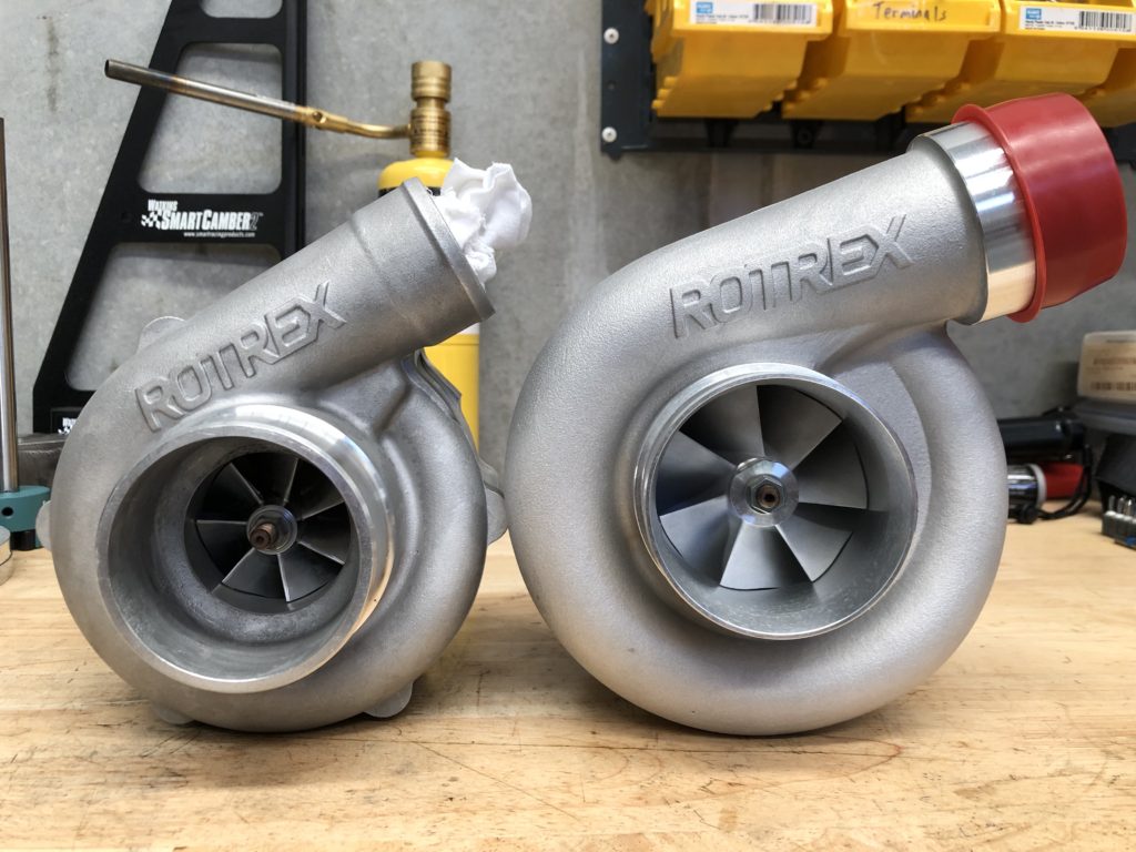
Below is a side by side photo of the C30-84 and C38-71. There is a considerable size difference.
Rotrex C30-84 left, Rotrex C38-71 right
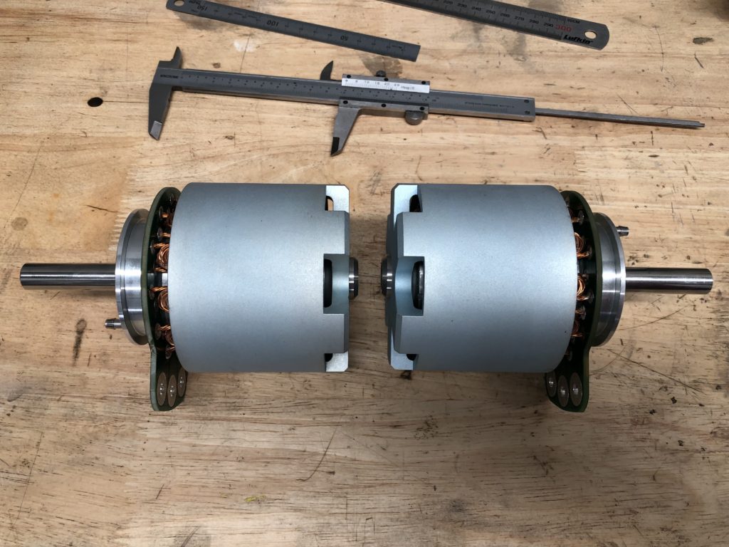
The C38-71 also has a different planetary gearbox with a lower ratio of 1:7.5 compared to the C30-84 at 1:9.49. Two new Lehner Torqstar 7050 motors were ordered with different winding turn count to best suit the new compressor. Below are the sizing calculations for the new motors.
As before these a liquid cooled units but in the industrial application construction which allows lugged connections to be used for phase cables.
Lehner Torqstar 7050 motors
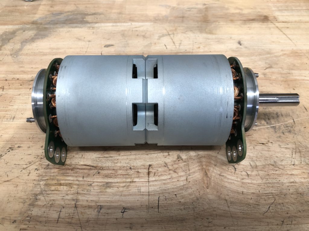
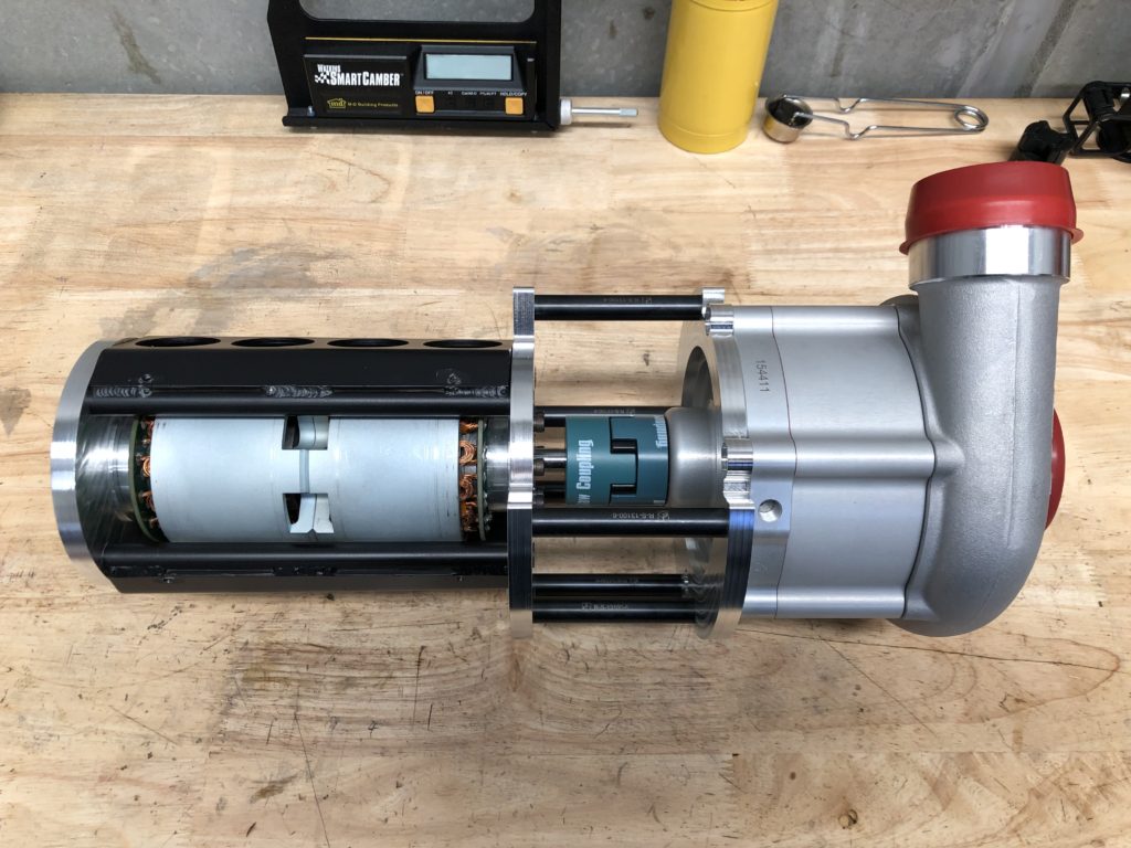
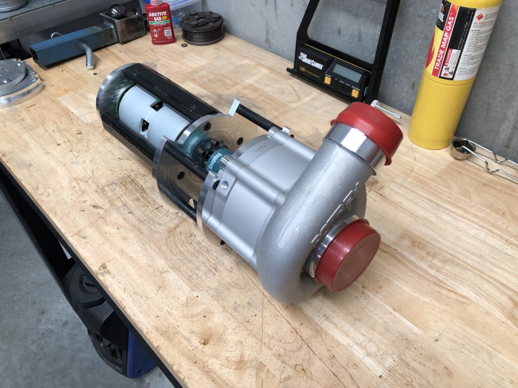
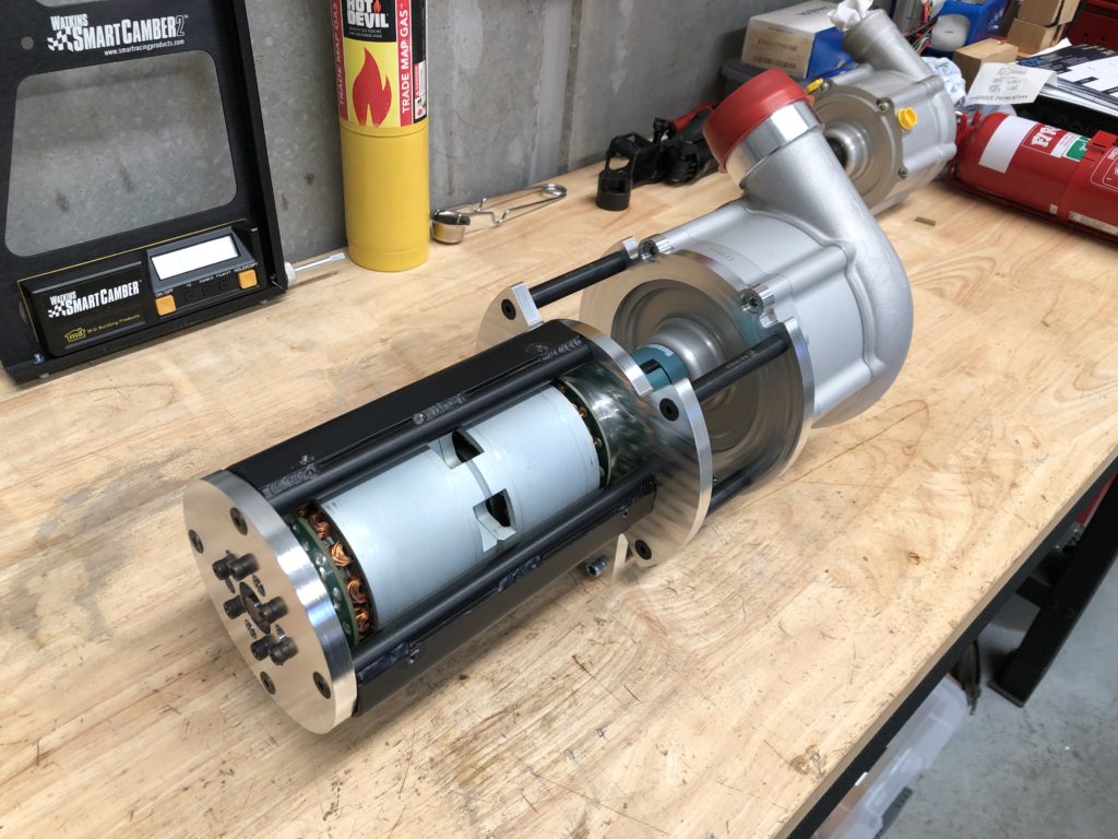
And as before the motors were combined onto a common 12mm drive shaft in a back to back configuration.
Electric motors with common drive shaft
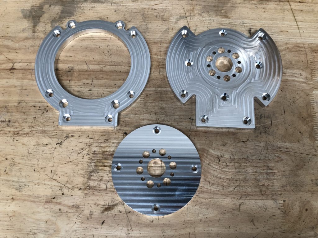
New new plates were designed, drafted and CNC machined out of 10mm thick 6061 Aluminium to suit the new setup.
CNC machined mounting plates
The complete unit looks much the same but the only carry over parts are the standoffs and torque tube halves. The drive coupler between the compressor and electric motors was upgraded to a L075 jaw coupler as the previous L070 coupler was chewing up the spider element due to operating above its rated torque level.
Finished electric compressor unitFinished electric compressor unitFinished electric compressor unit