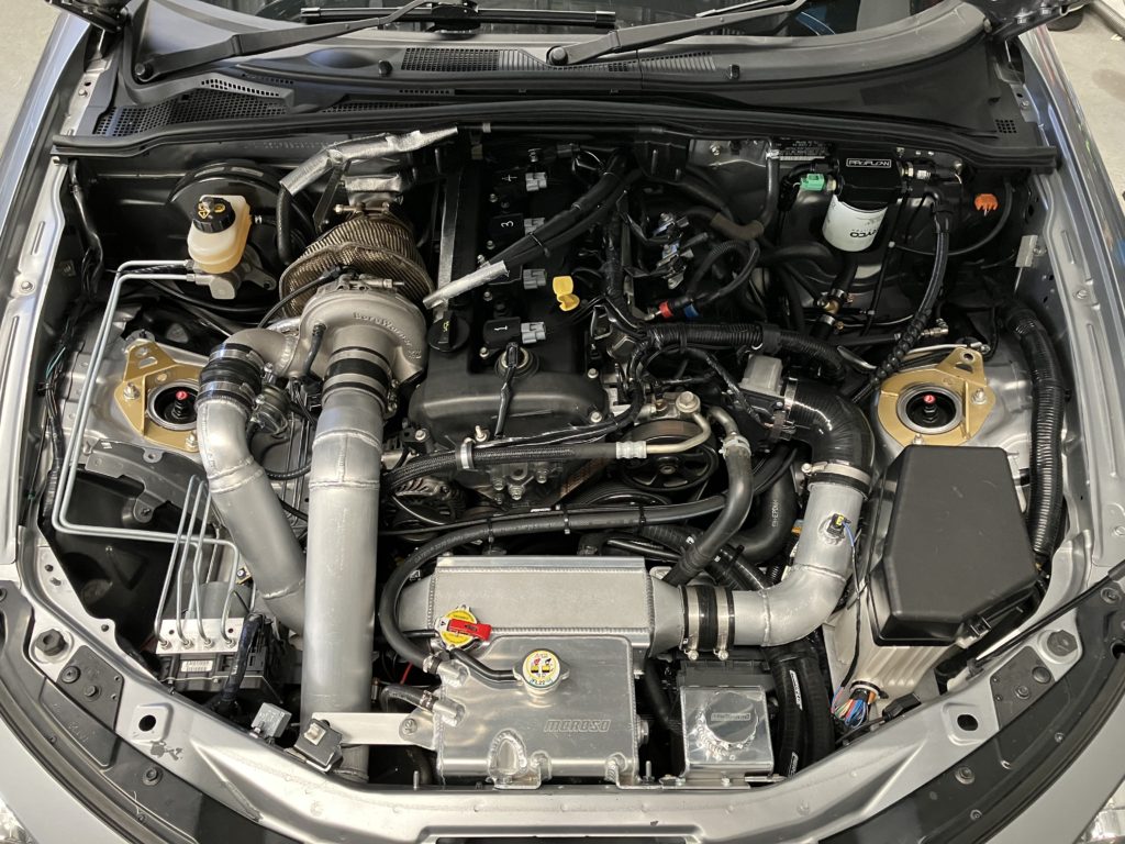
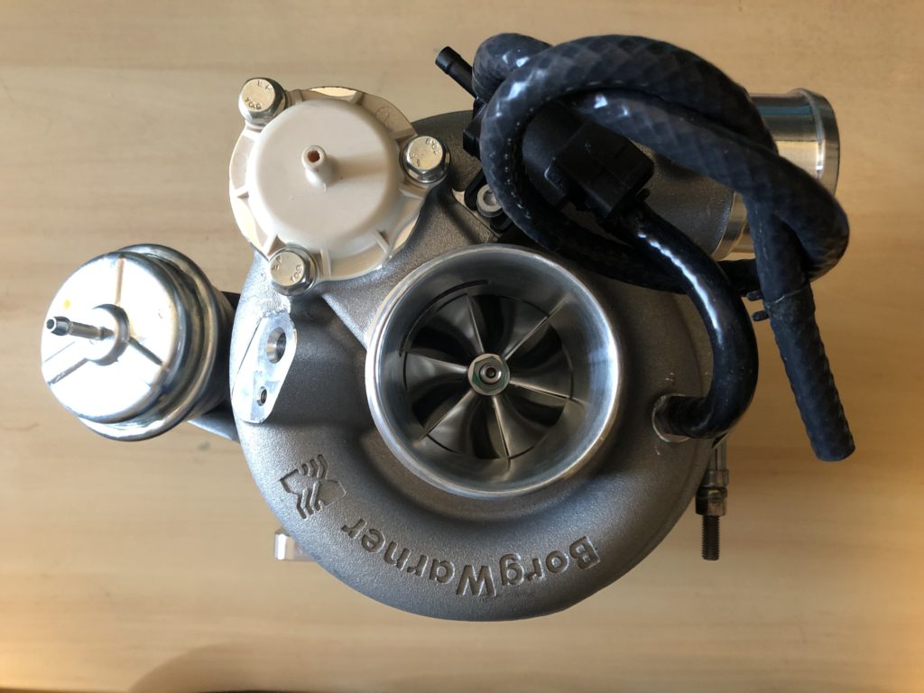
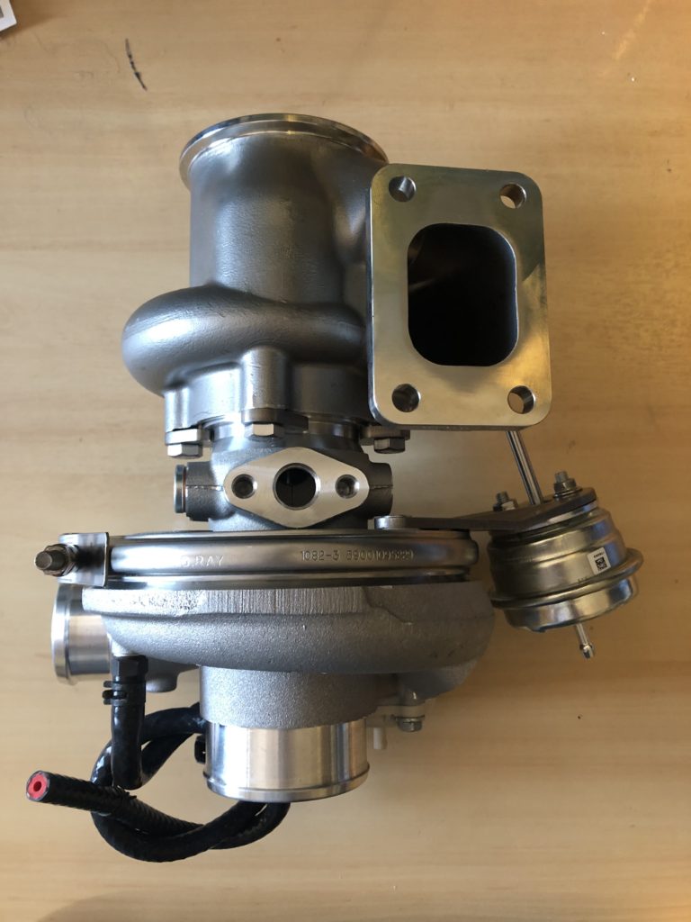
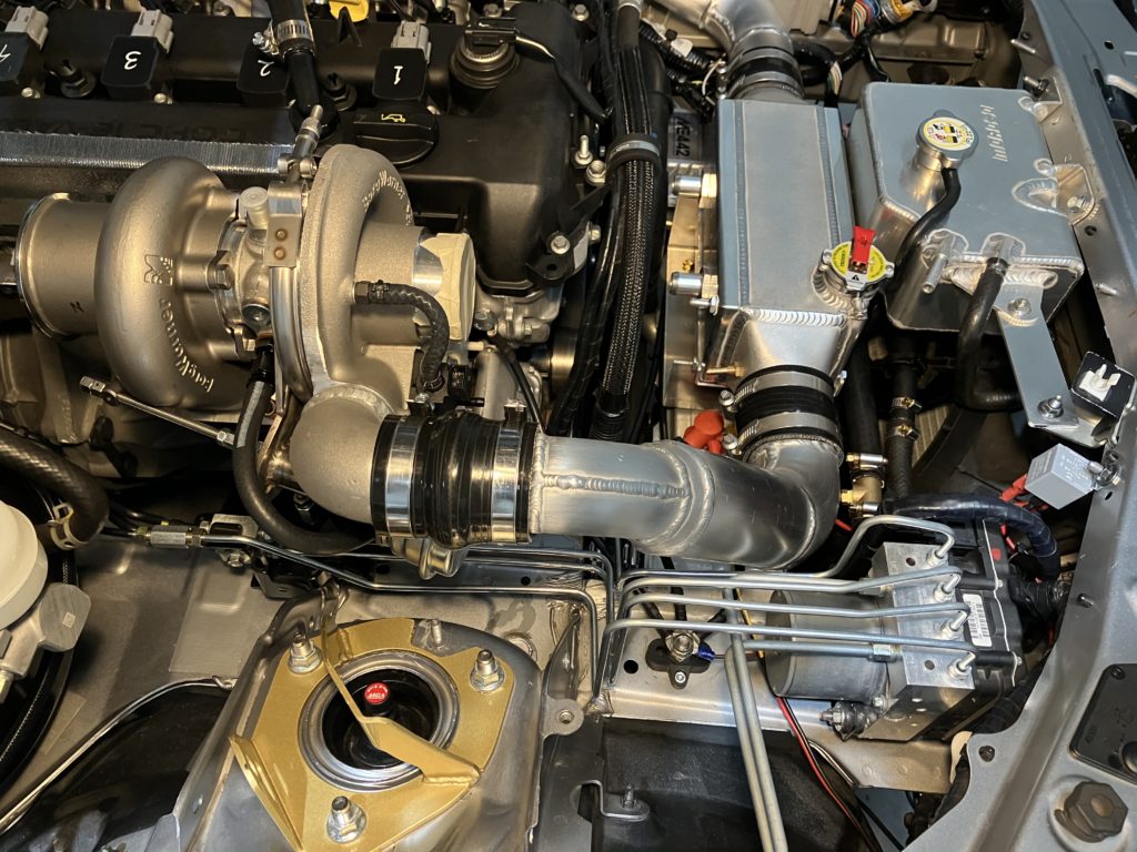
The turbo selected is the Borg Warner EFR6758 which is good for 500 HP. It was ordered with internally wastegated 0.85 A/R turbine housing, T25 turbine inlet, and v-band turbine outlet. It has ceramic ball bearings in an aluminium center housing so will need to be water cooled.
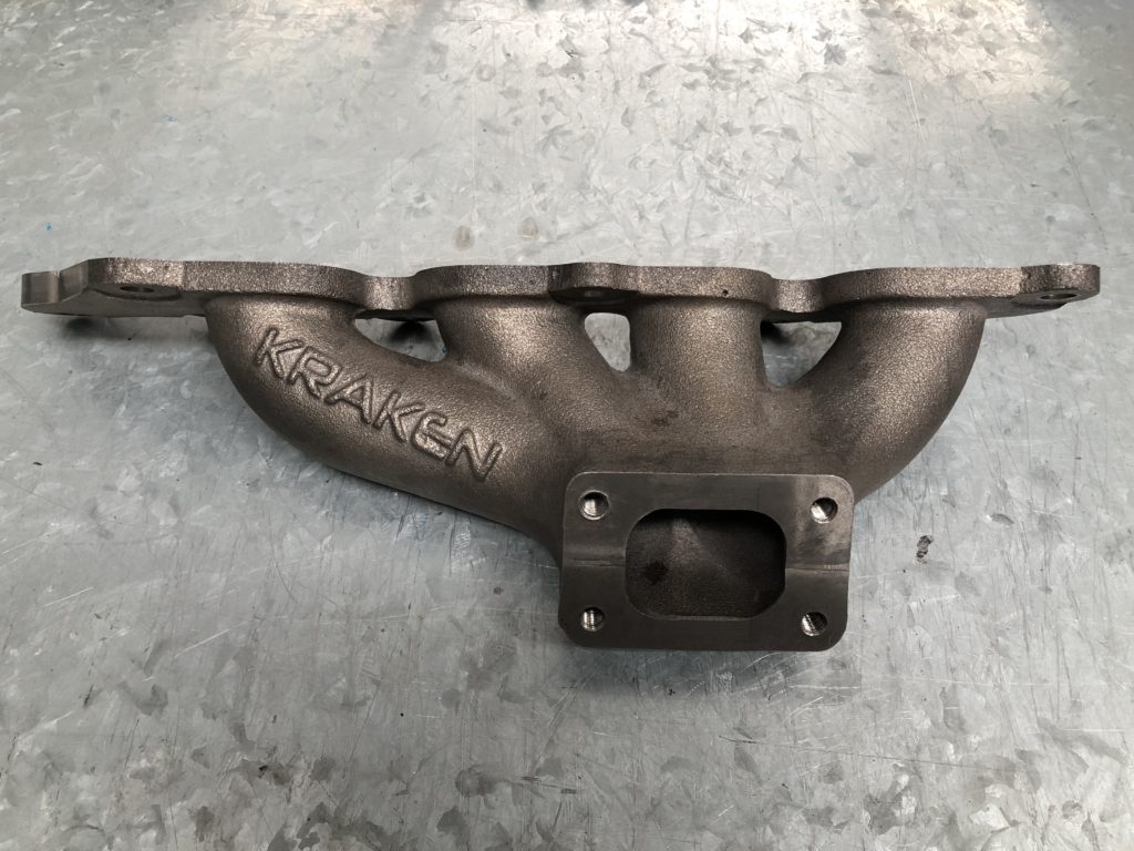
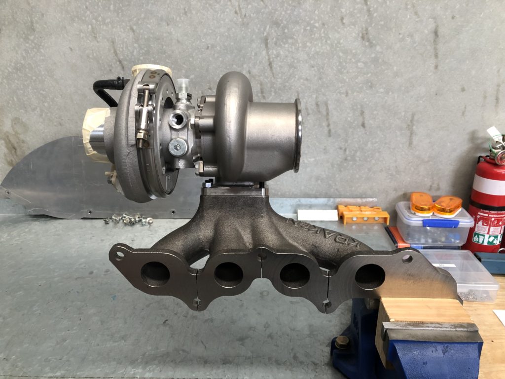
For the exhaust manifold options are limited. Low mount turbo manifolds don’t work on right hand drive MX-5s as the steering column goes right through where the turbo would sit. I wanted to go with a cast manifold, mainly for reliability so ordered a Kraken top mount manifold.
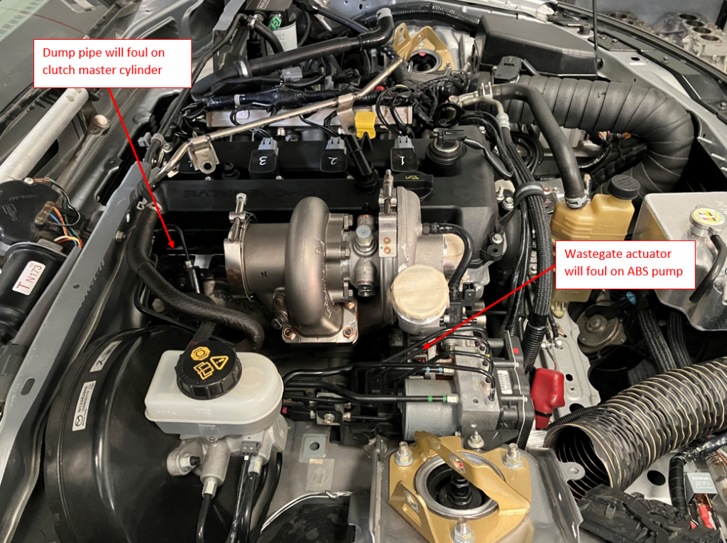
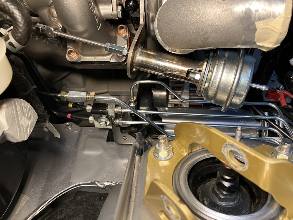
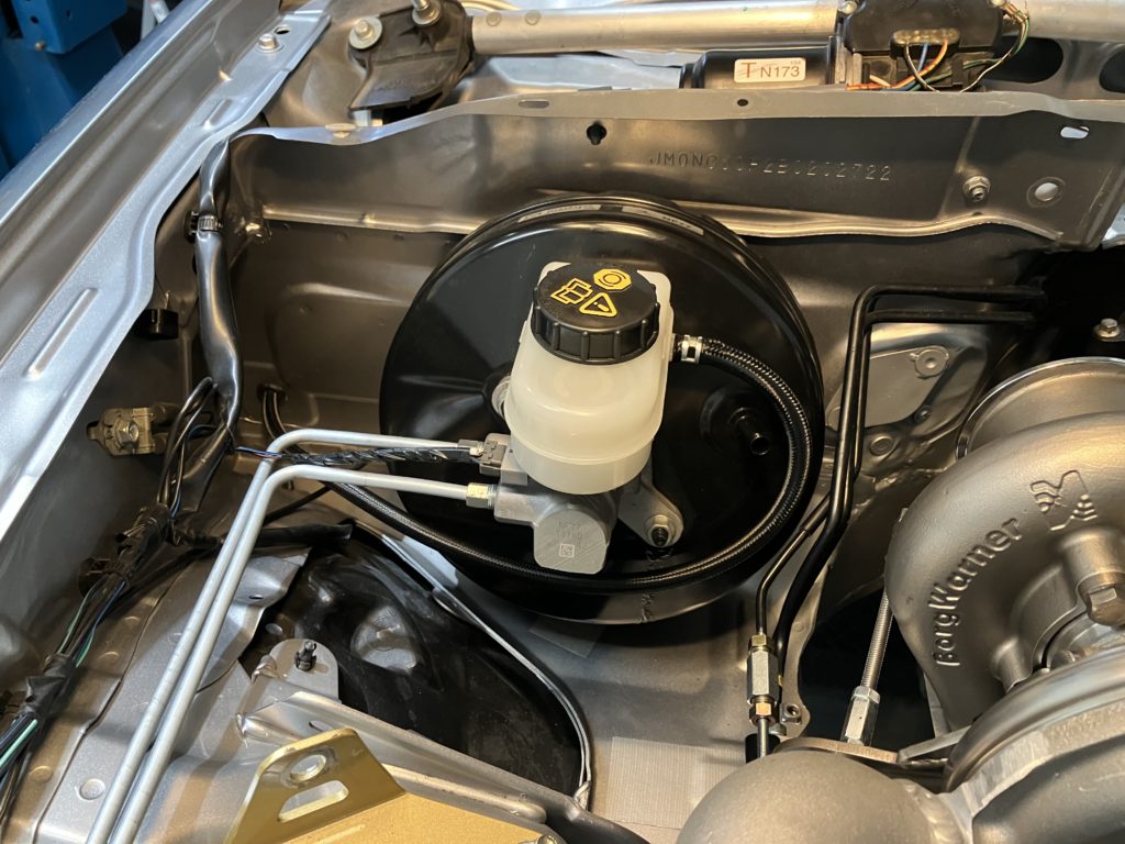
Turbo and manifold were mocked up to the engine to determine intercooler pipework routing and any clearance issues. Three issues became immediately obvious. First the turbo sits high in the engine bay and the comprosser outlet was fouling on the bonnet. Second the wastegate actuator and ABS pump want to occupy the same space. And the third was the clutch master cylinder is right where the dump pipe will be. The clutch master cylinder issue is another problem that presents in RHD drive turbo installs and not LHD.
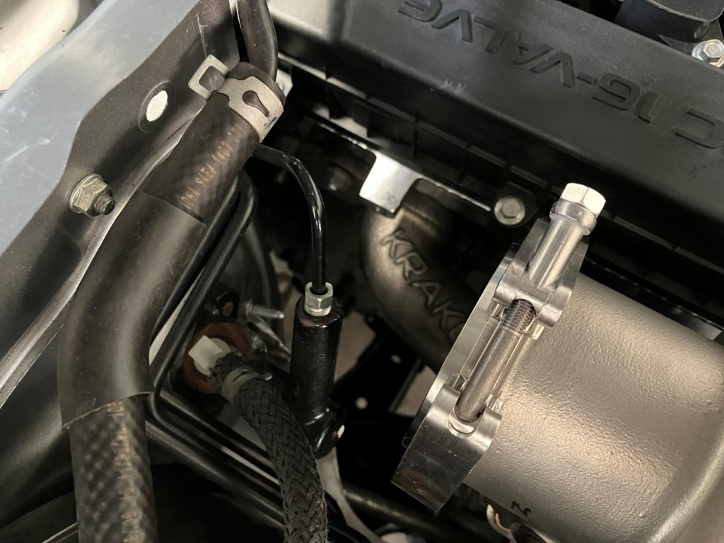
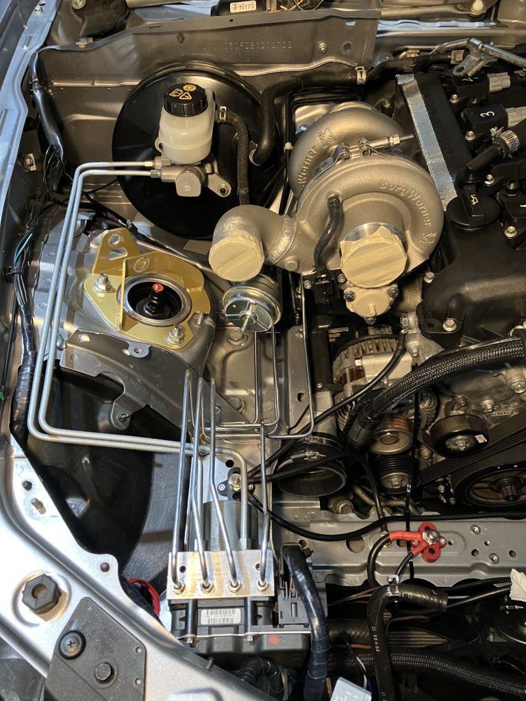
To solve the bonnet clearance issue a 2″ aluminium 90-degree elbow was welded directly to the compressor scroll. Also, the wastegate actuator mount was modified extended the wastegate actuator forward and allow the compressor housing the be counter clocked further clockwise.

To solve the ABS pump clearance issue the pump was relocated as far forward on the chassis rail as possible. The two brake lines between the master cylinder and ABS pump were remade with 1/4″ double-walled bundy tube. The four lines from the ABS pump to each brake caliper were extended using 3/16″ double-walled bundy tube.
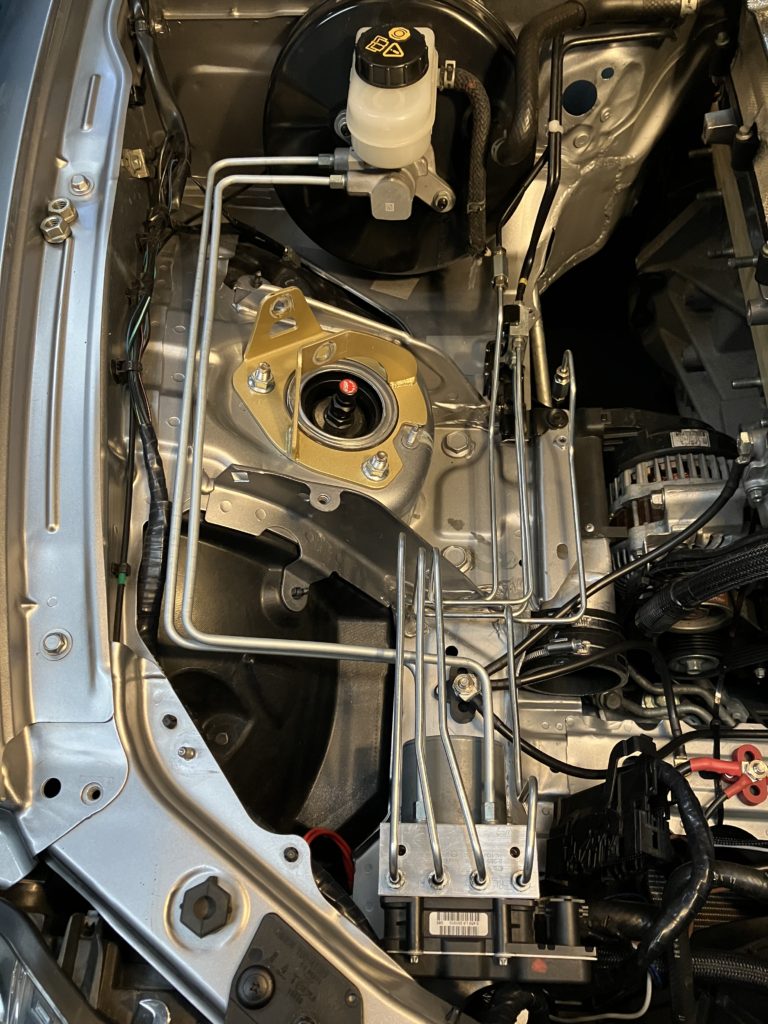
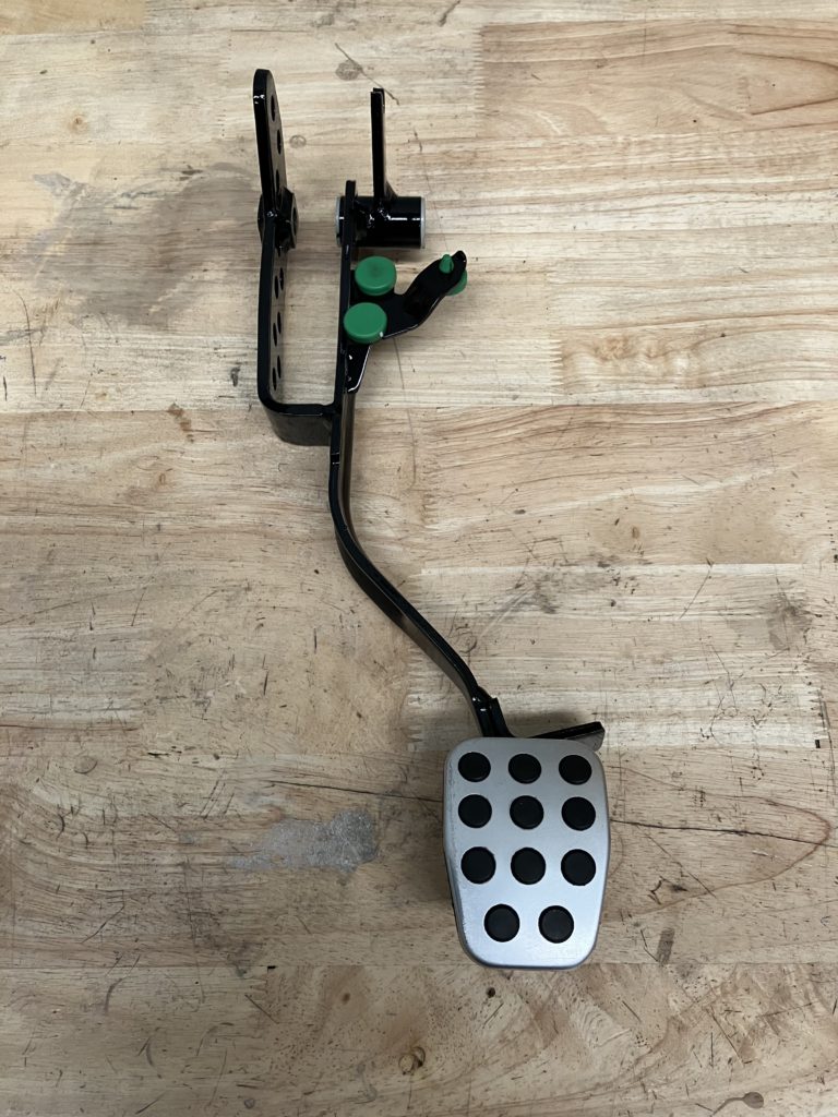
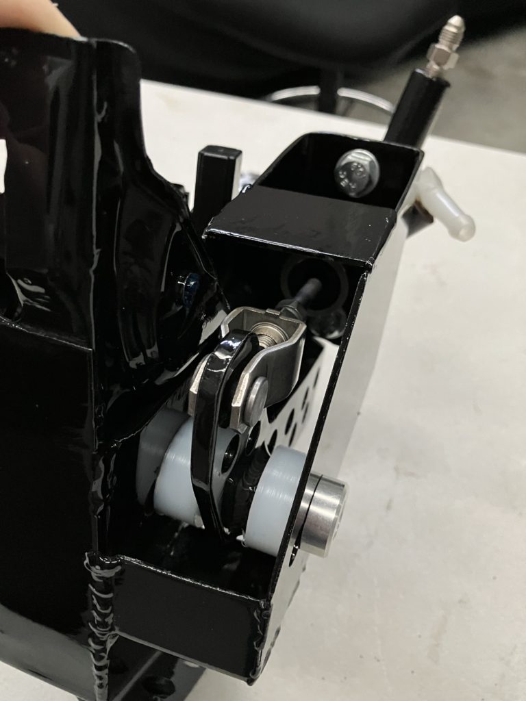
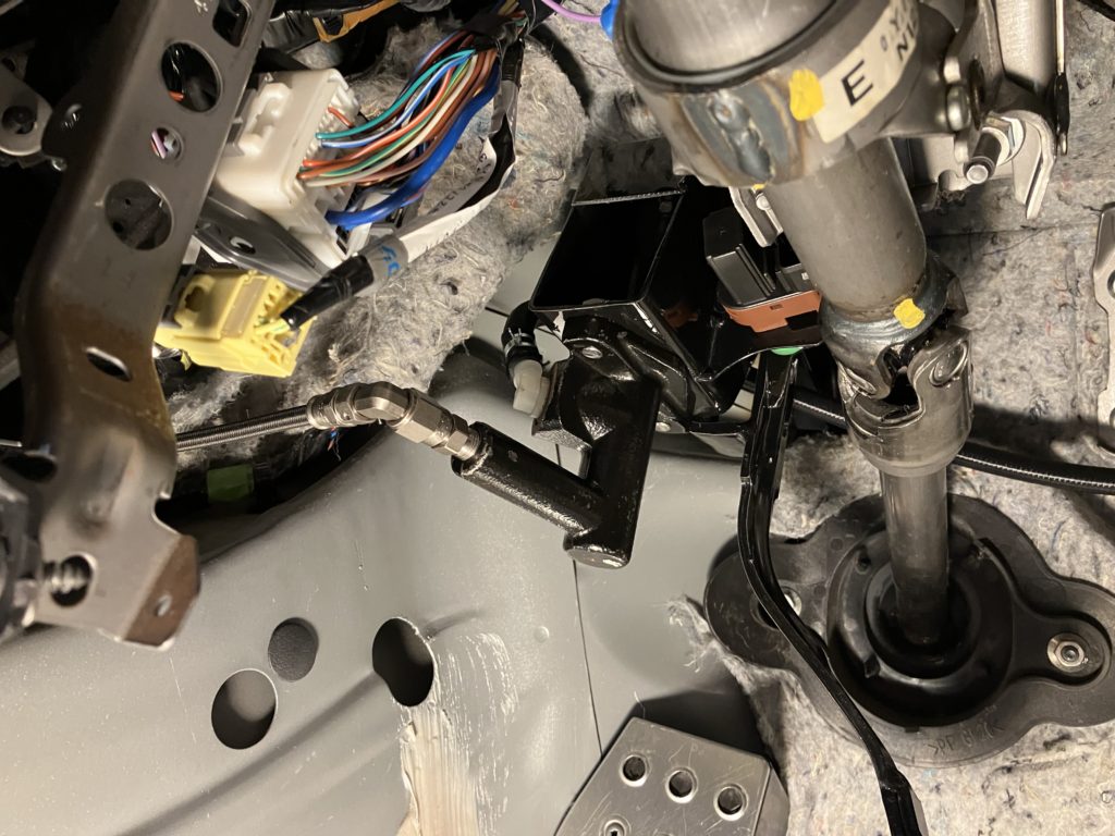
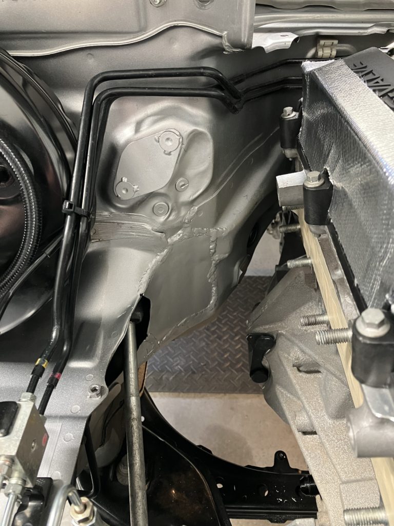
The final clearance issue was the most difficult to solve. The clutch master cylinder could not stay where it was. It was decided to move it inside the cabin. The clutch pedal assemble was removed from the car for modification. The pedal itself had second lever arm welded on. The pedal assemble was modified to mount the master cylinder to it. The whole assemble was reinforced as this is a week point on these cars.
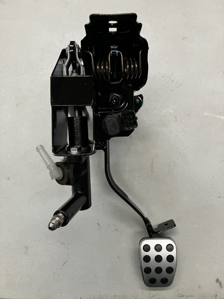
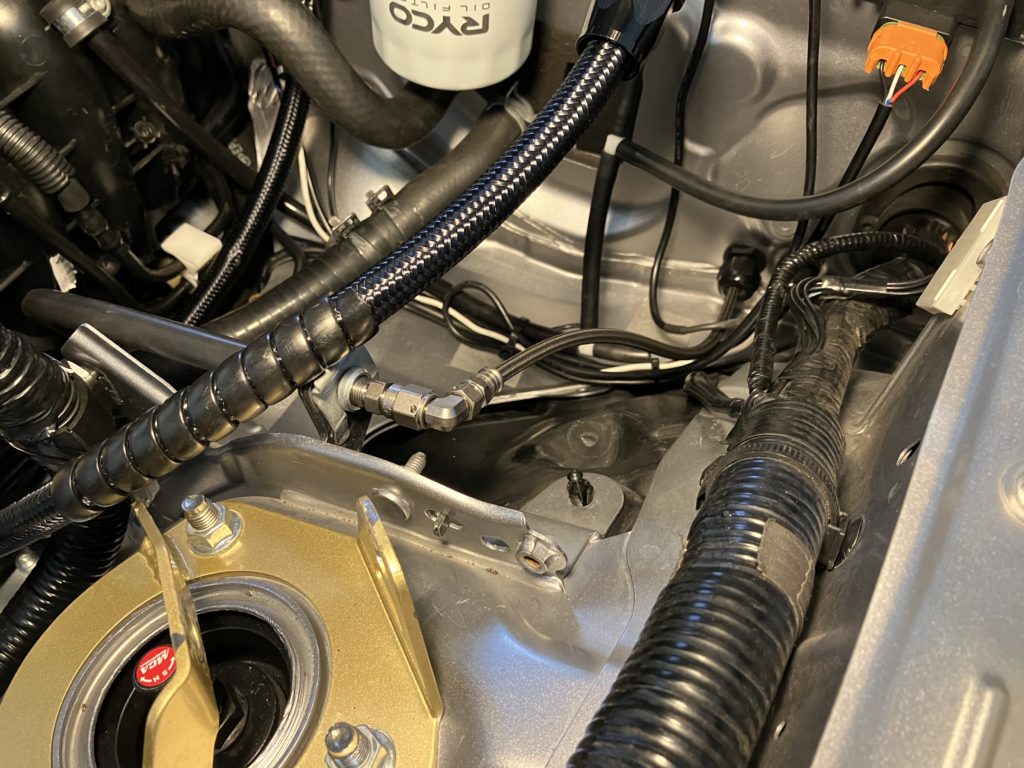
Low pressure hose was run from the brake fluid reservoir, through the firewall on the driver’s side, to the suction of the master cylinder. For the outlet of the master cylinder high pressure AN3 braid hose was run under the dash, through the firewall on the passenger side, and then picking up the OEM soft line running down to the clutch slave cylinder.
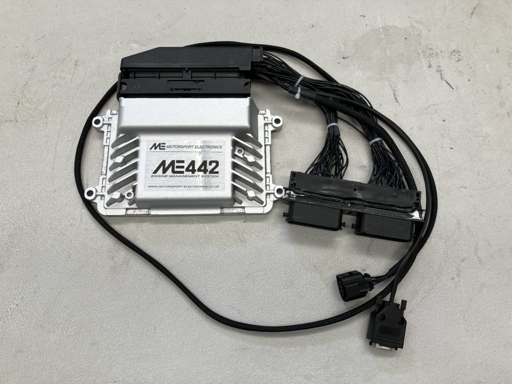
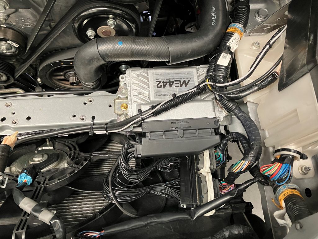
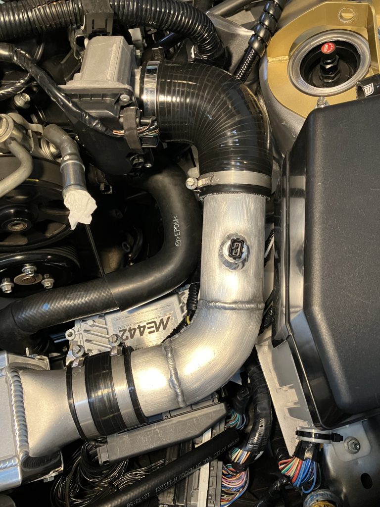
As part of the turbo install the factory ECU is being replaced with a Motorsport Electronics ME442. At 10psi the factory mass air flow sensor was close to being maxed out even though it is already mount in 3″ tube. Using the ME442 allows for VE Based fueling using manifold air pressure only. It also allows for boost control to be brought inside the ECU using RPM and throttle position. This will be important when reintroducing the electric supercharger.
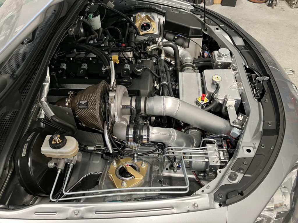
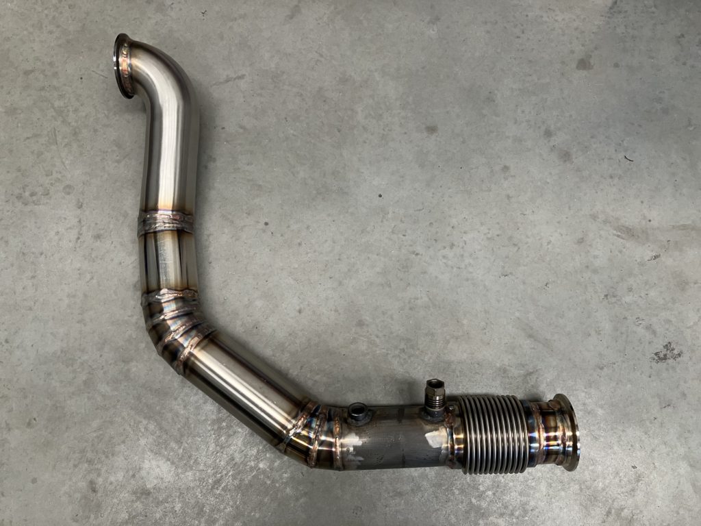
Next step was fabricating the dump. As well as relocating the clutch slave cylinder, the firewall was massaged slightly to give extra clearance. Coming out of the back of the turbo a tight radius mandrel 90-degree bend was used with the remainder made of straight and pie cut 3″ 304 stainless steel tube.
So naturally the intercooler will be relocated to the front of the car. It sits directly in front of the engine to keep intercooler pipework as short as possible and removal of the MAF sensor has helped this cause. Removal of the MAF means we have to install an intake air temperature sensor downstream of the intercooler.
The outlet of turbo is 2″. We immediately expand out to 2.5″ and maintain this diameter through the intercooler and all the way to the throttle body.
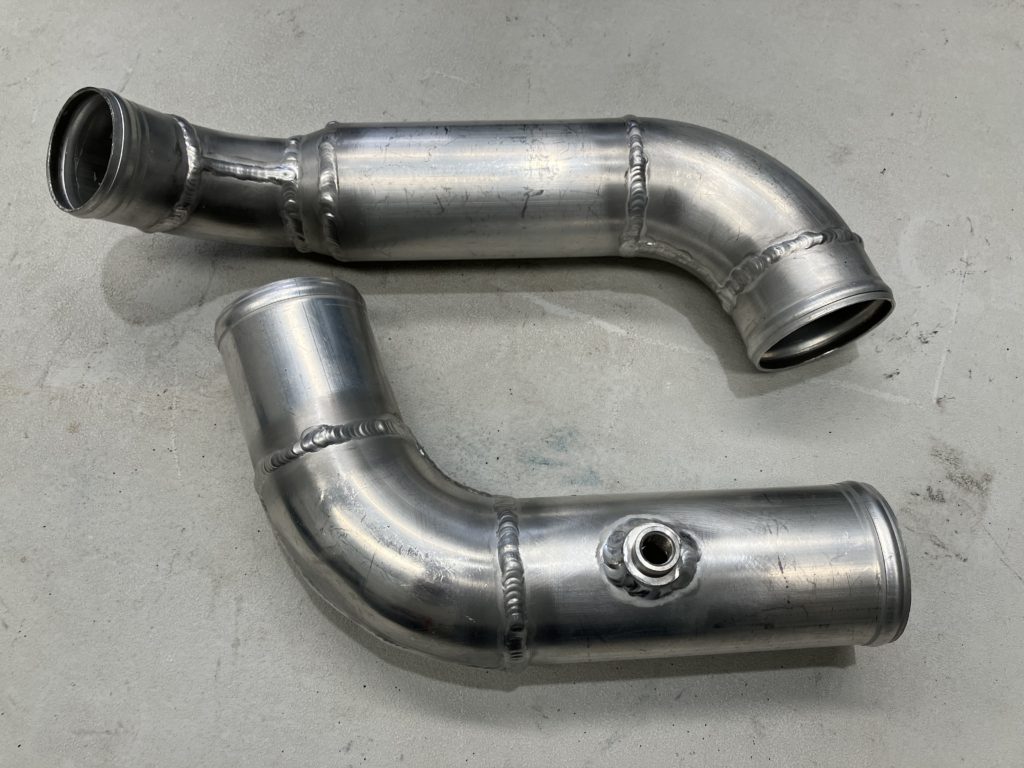
Turbo inlet pipework was fabricated to draw cold air from behind the front bumper but in front of radiator.
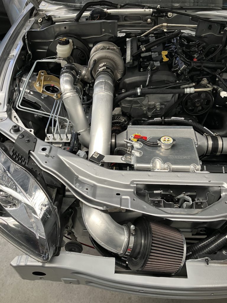
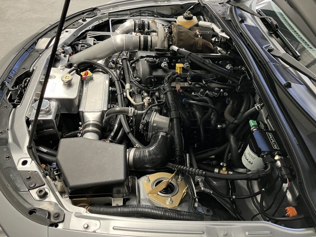
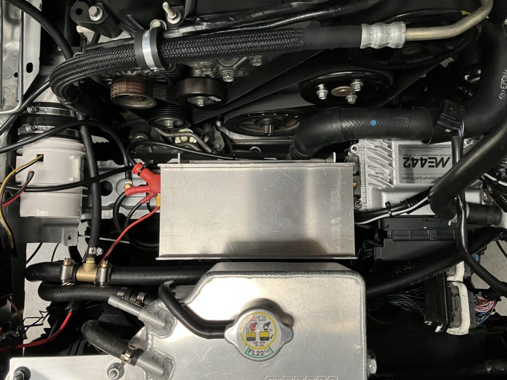
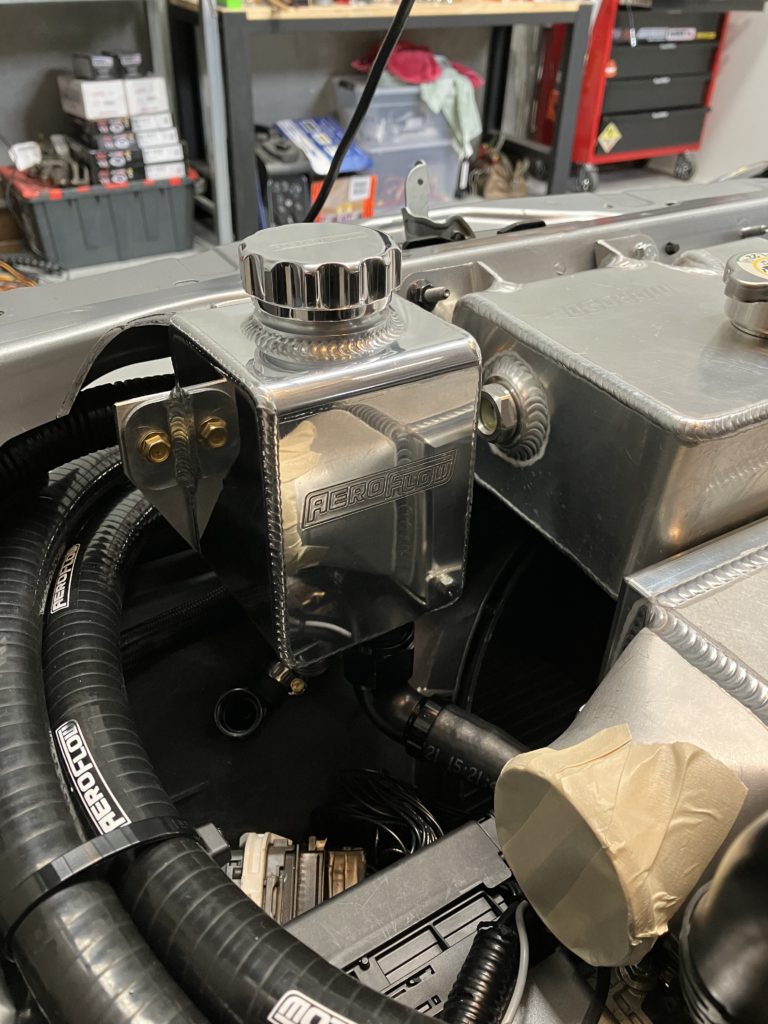
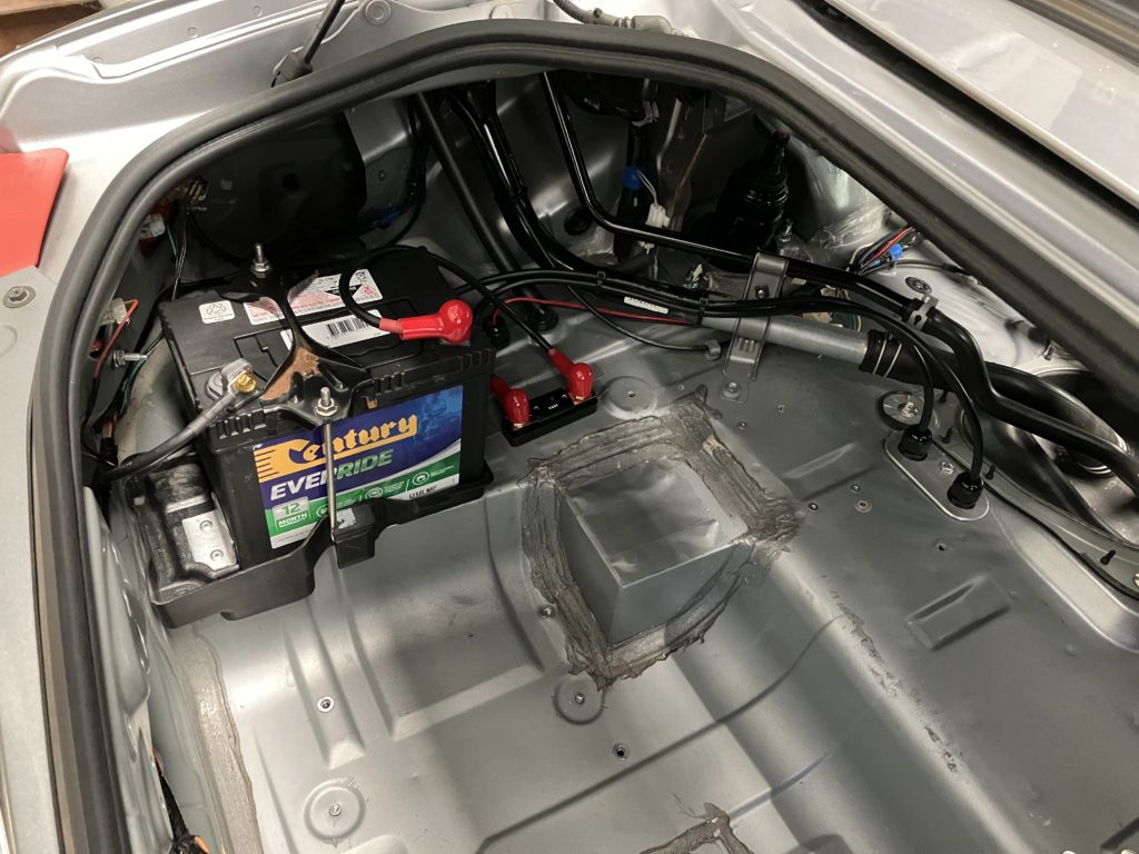
The intercooler and pipework required the removal of the battery and power steering reservoir from their OEM locations. An aluminium power steering reservoir has been mounted next to the coolant expansion tank. The battery has been moved to the boot.
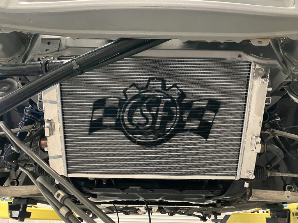
There is no way the tiny OEM radiator is going to keep up with the cooling demands on the new turbo setup. Besides the extra cooling demand form the extra power that will be produced, we are also using engine coolant to cool the oil and now the turbo as well. A CSF high performance radiator has been installed. This unit is considerable thicker than stock and is all aluminium design so don’t have to worry about plastic end tanks failing.
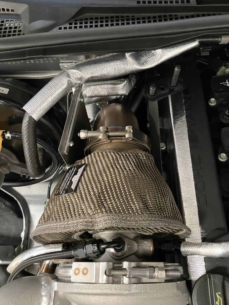
To manage under bonnet temperatures and protect temperature sensitive components heat shielding was installed around the turbo and dump. For the turbo a PTP blanket was used to cover the turbine housing. Heat reflective tape was used on the firewall and rocker cover, heat reflective sleaving was used to protect hoses and brake lines, and some heat shields were fabricated.

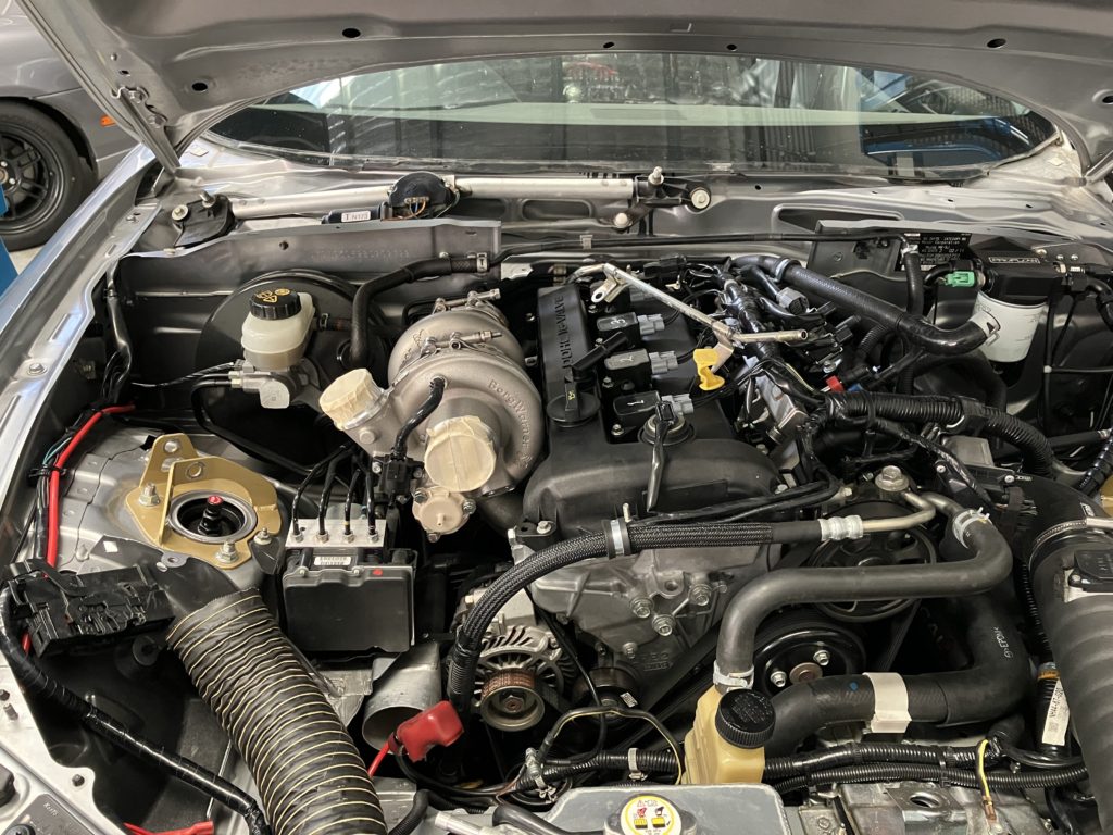
Turbo install complete and ready for testing and tuning.