This is where things get a bit tricky. The plan was to run 2.5 inch aluminium tube from the compressor in the rear all the way to the engine bay. Just before the throttle body the diameter will increase to 3 inch and the factory mass air flow (MAF) sensor would be mounted in this section.
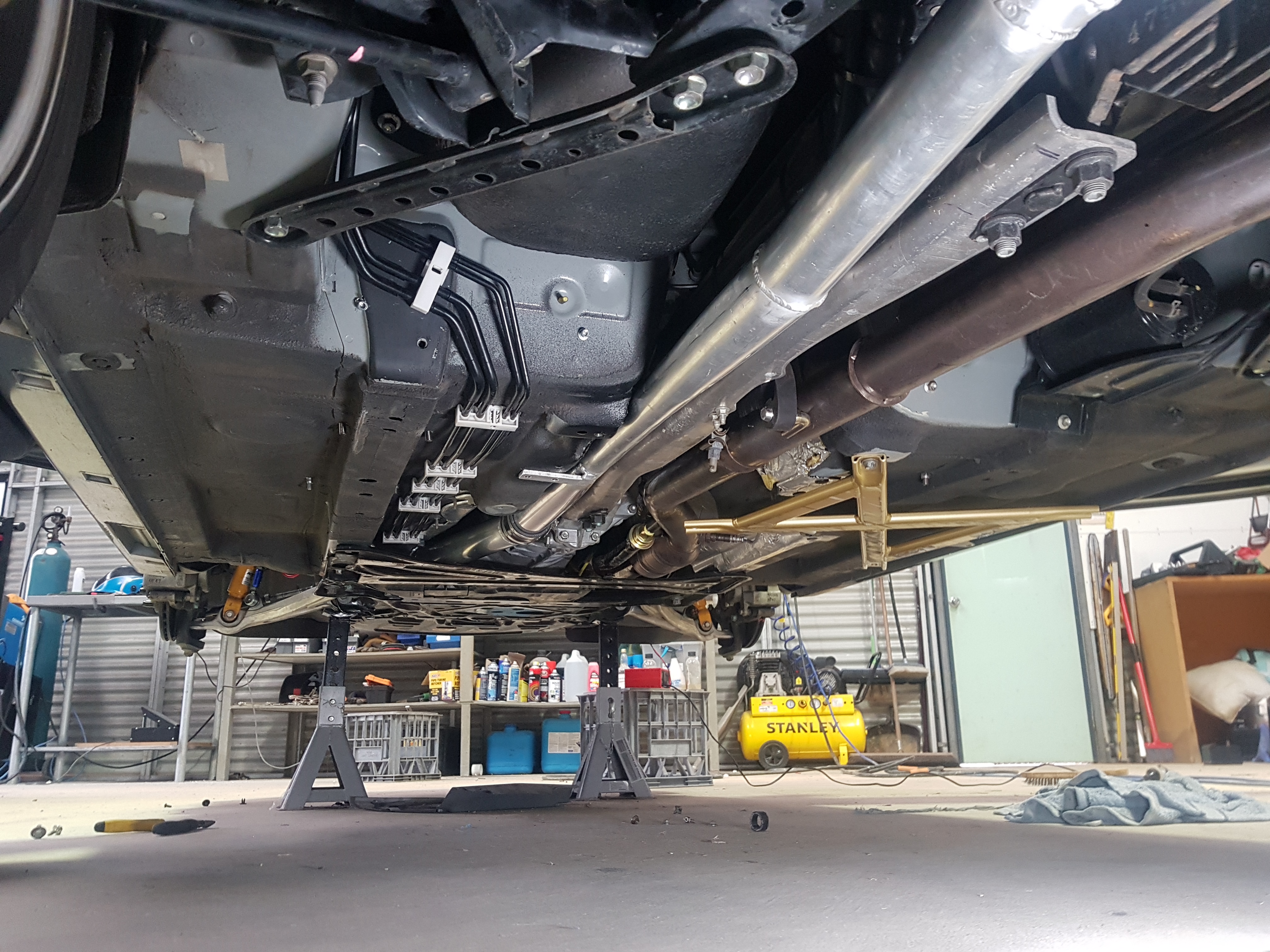
After passing through the floor in the boot the charge pipe goes under the diff.
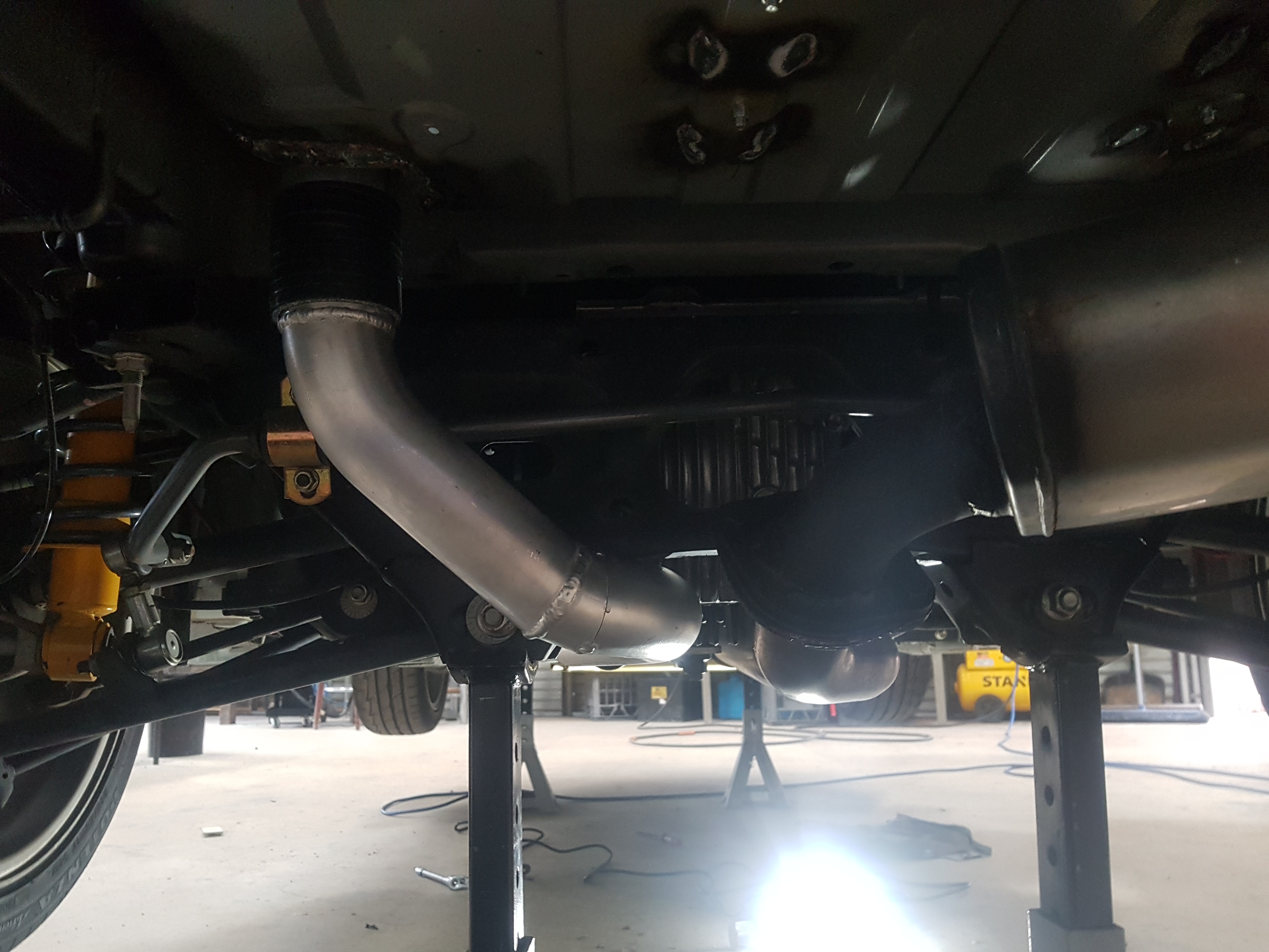
As the exhaust is on the right hand side of the gearbox and power plant frame (PPF), the charge pipe will need to be installed on the left hand side of the PPF. It became clear that clearance would be an issue.
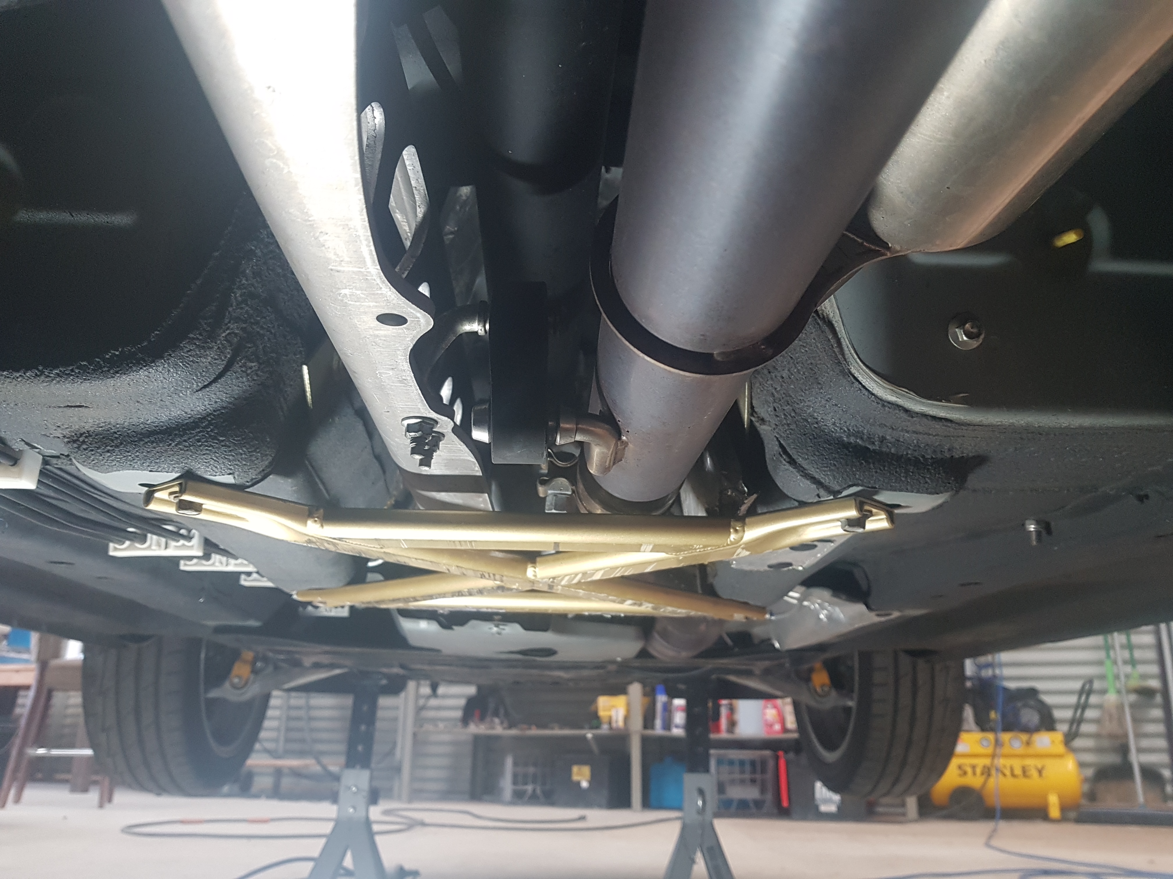
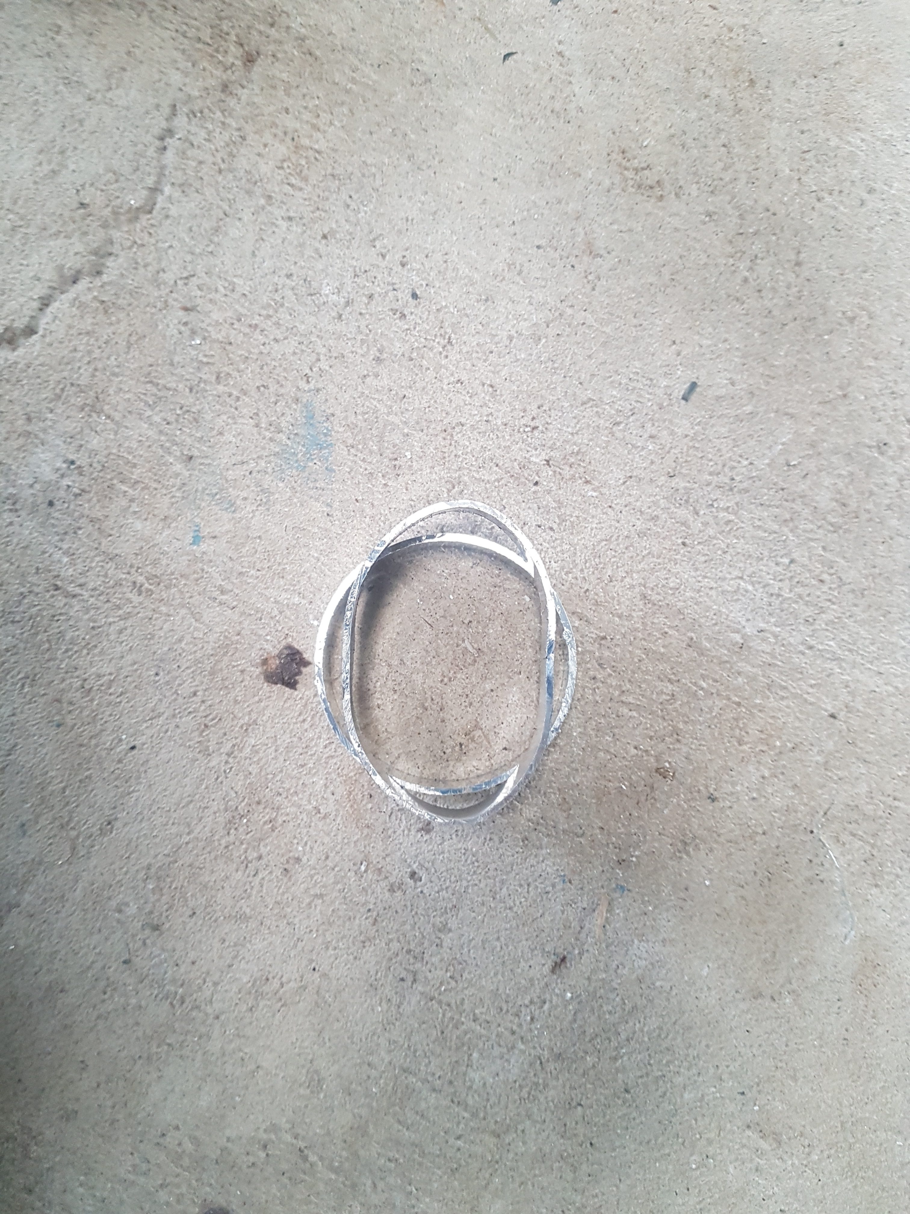
To get the tube through this space it would need to be crushed slightly to create an elliptical rather that circular cross section. This will not have a material effect on flow or pressure drop through this section. The transmission tunnel was also massaged to gain extra clearance.
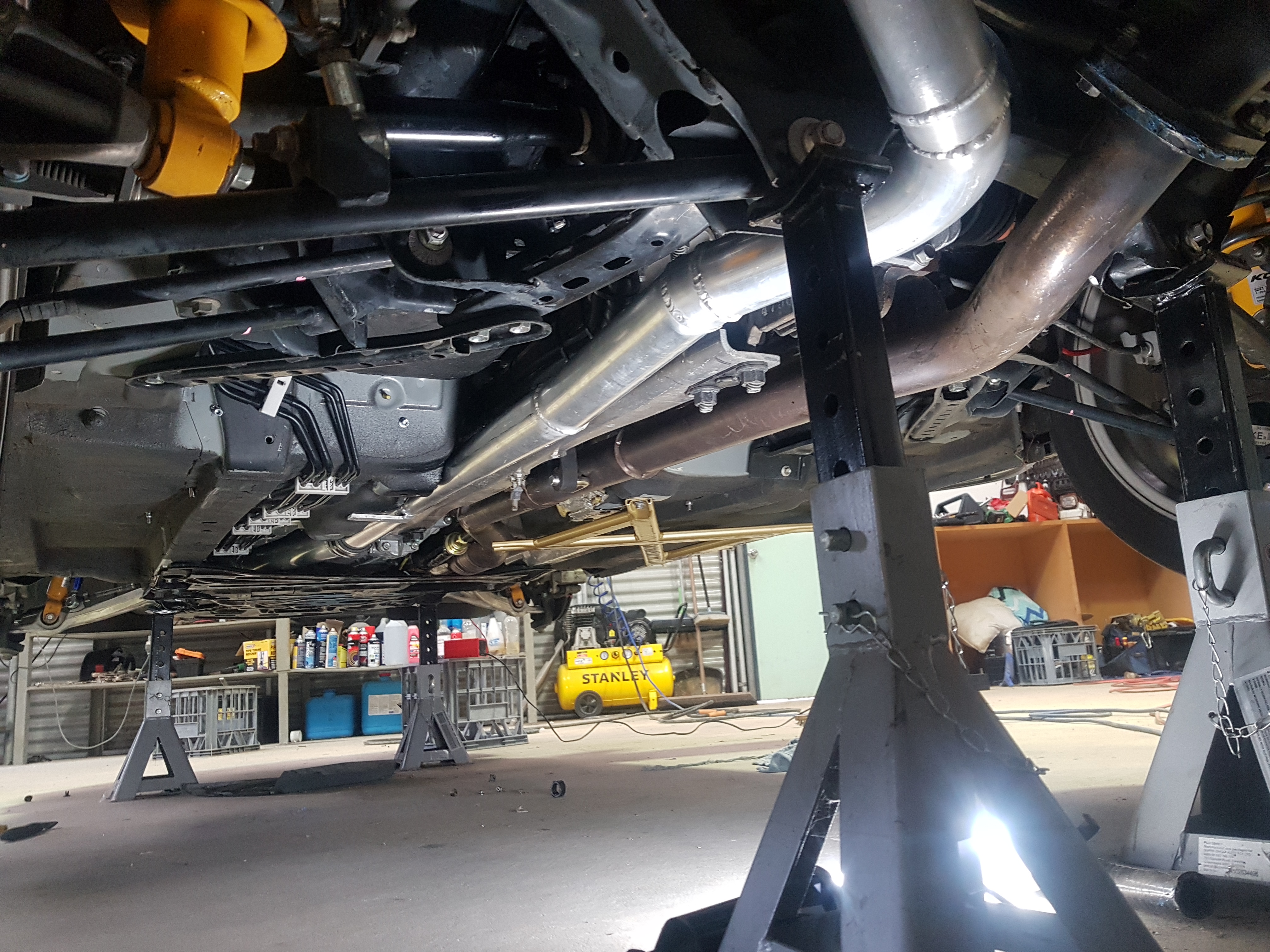
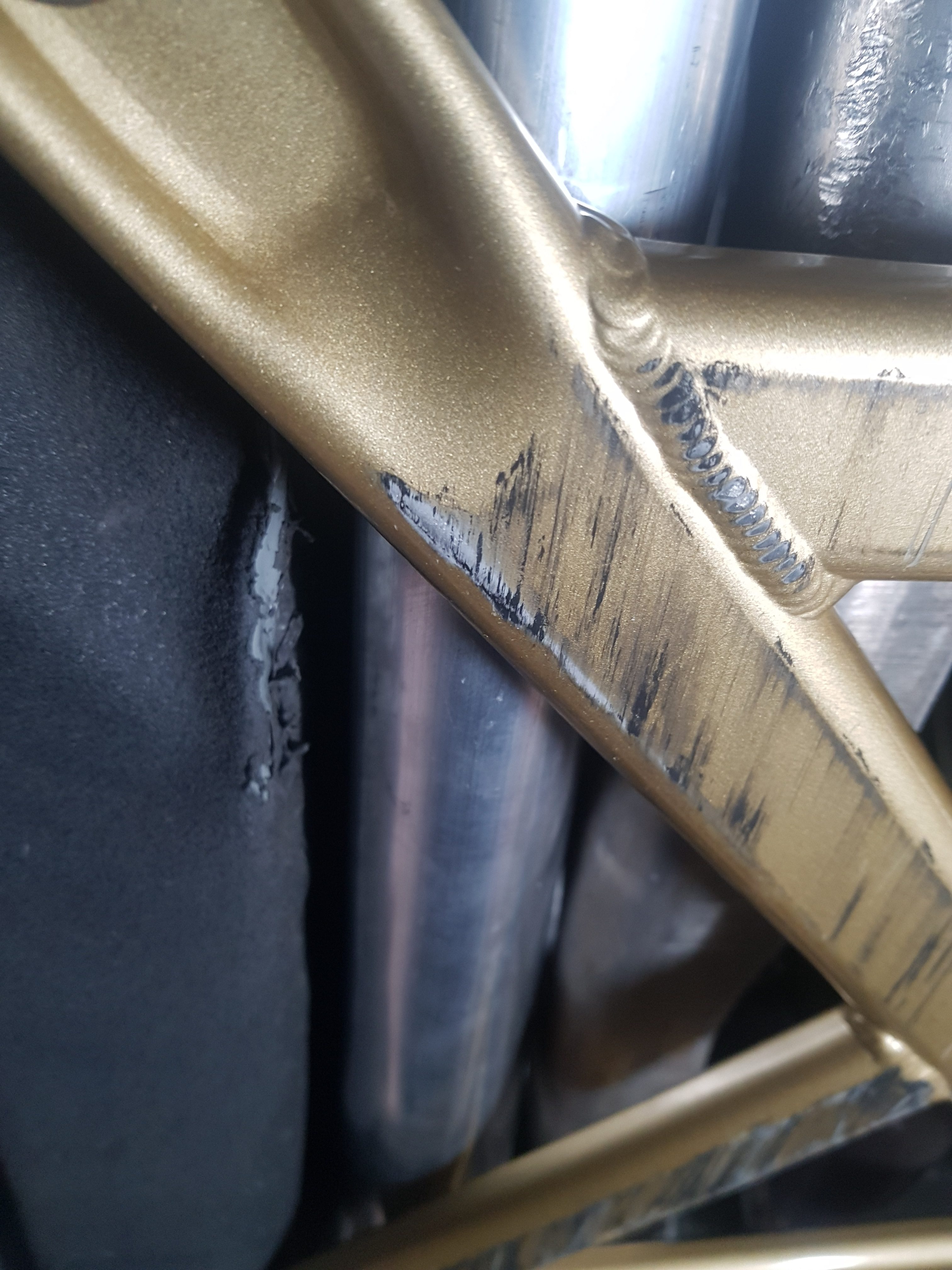
The tube fits above the under body cross brace so should be out of harms way. Although it doesn’t look it in the below pictures there is 10mm clearance either side of the charge pipe as it passes between the transmission tunnel and the PPF.
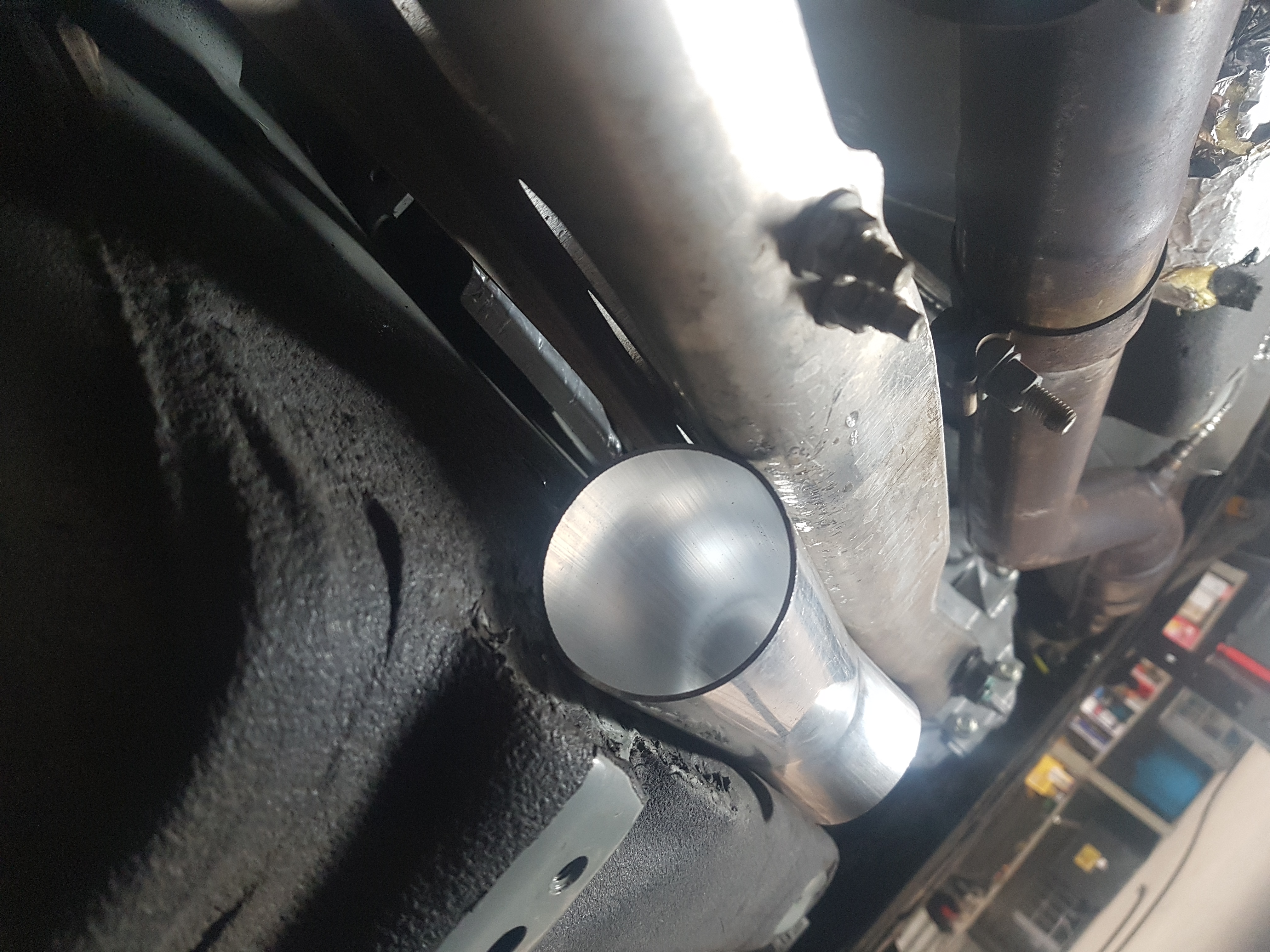
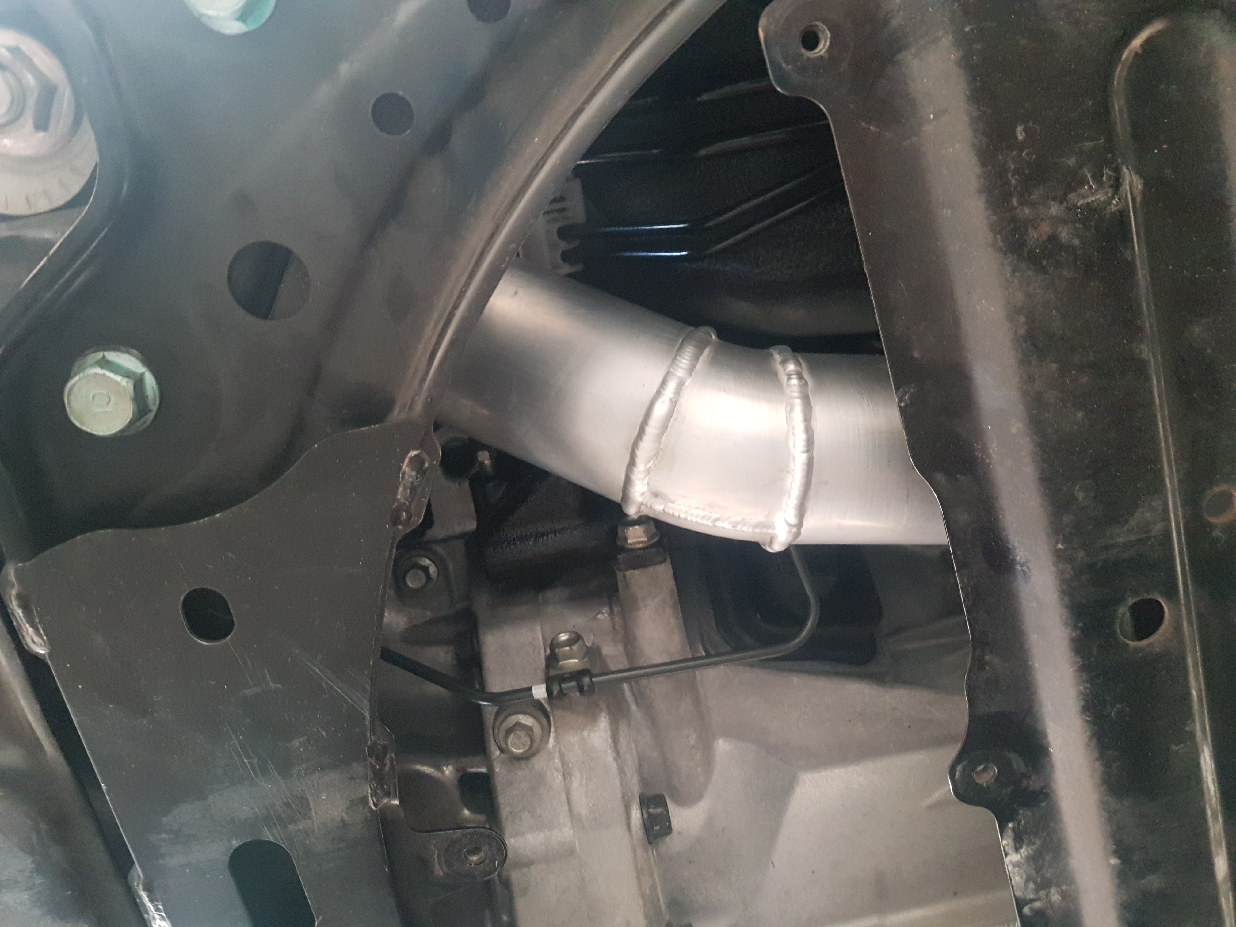
The next joint in the tube is at the gearbox output shaft after which the tube makes its way around the gearbox and bell housing.
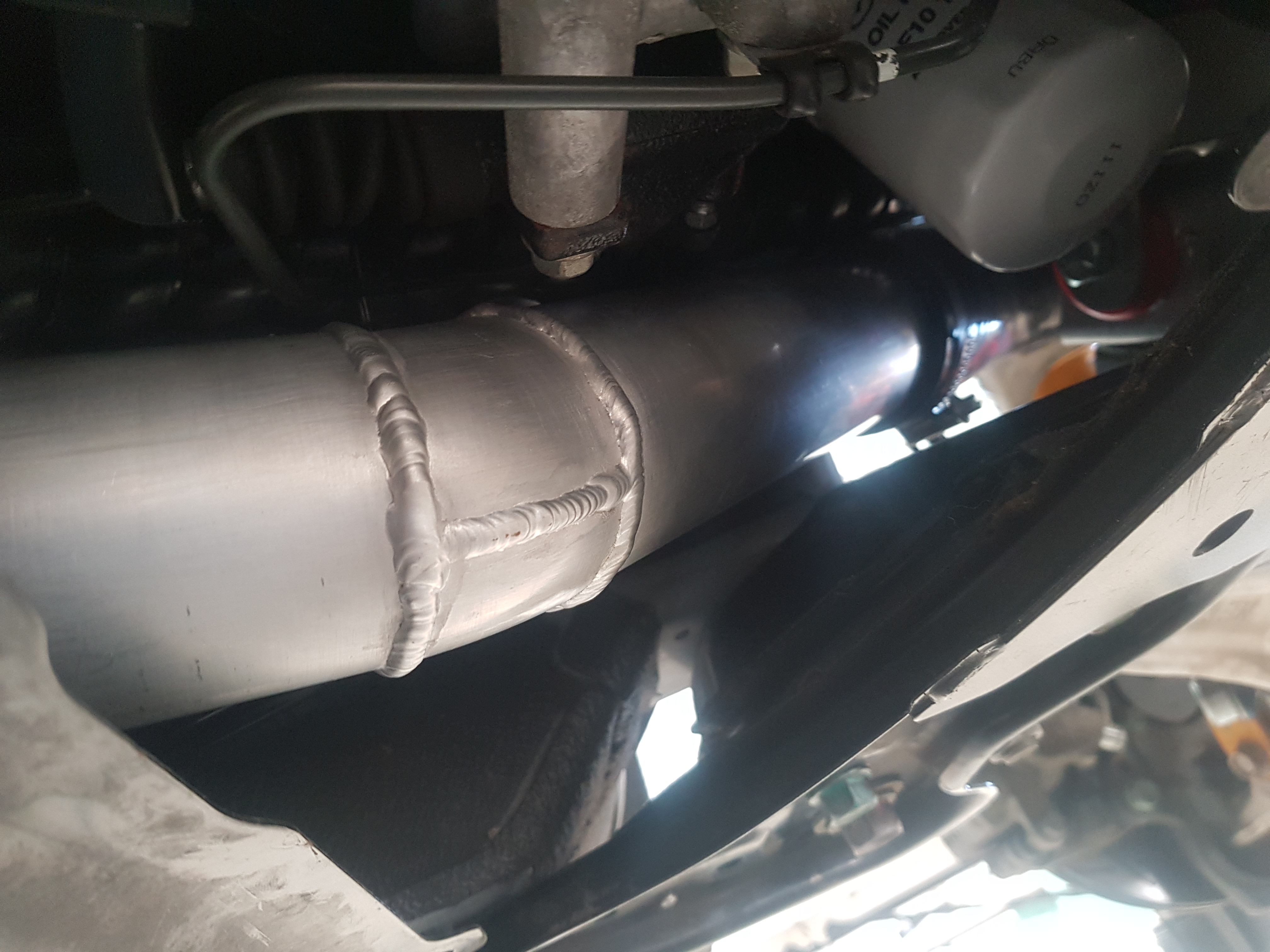
From the bell housing the tube runs along the left hand side of the motor around the left engine mount. At this time the factory engine mounts were replaced with polyurethane mounts. These mounts are physical smaller than the factory mounts allowing more room for the charge pipe. They will also better handle the increase in torque from the supercharged engine.
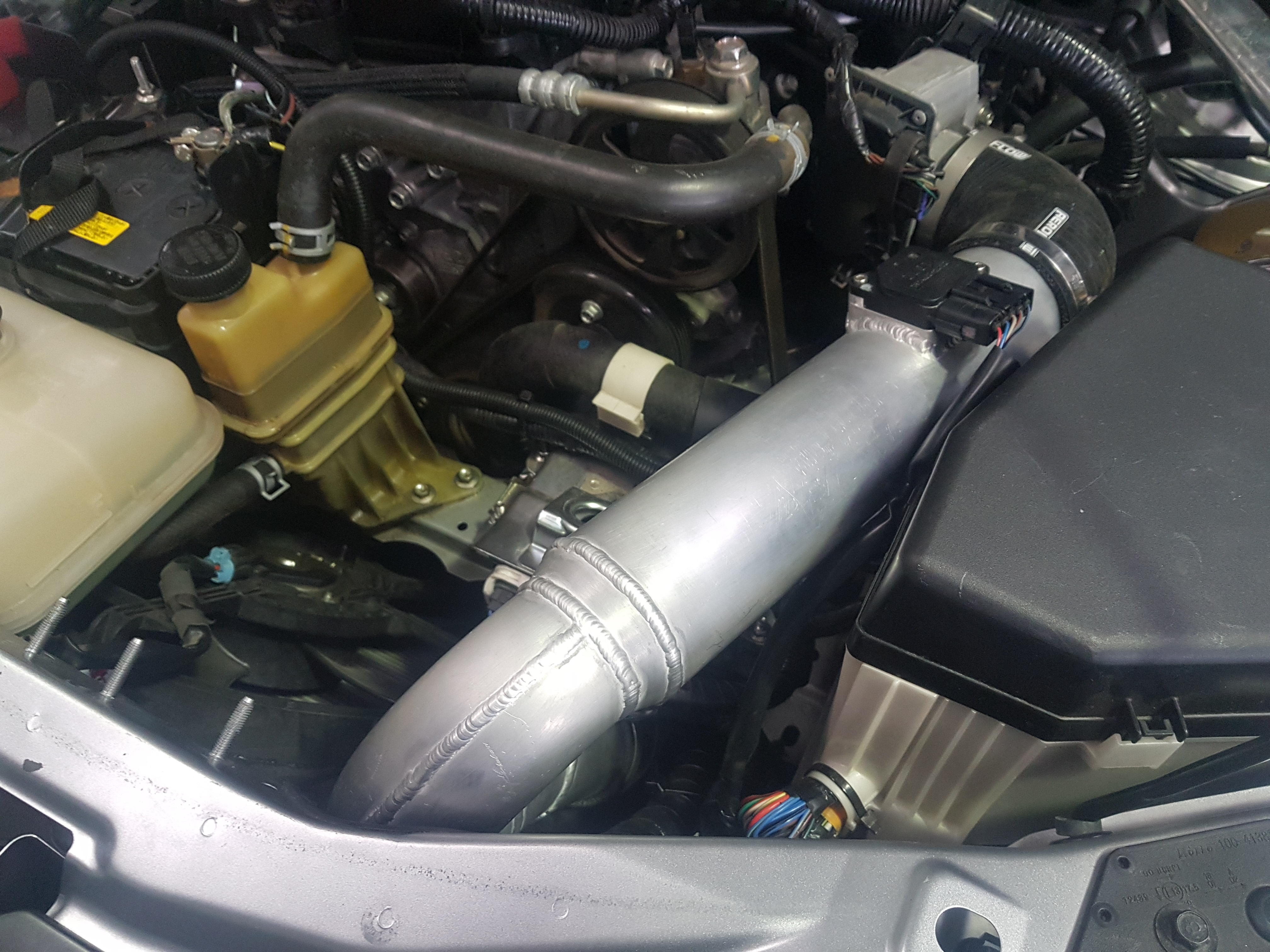
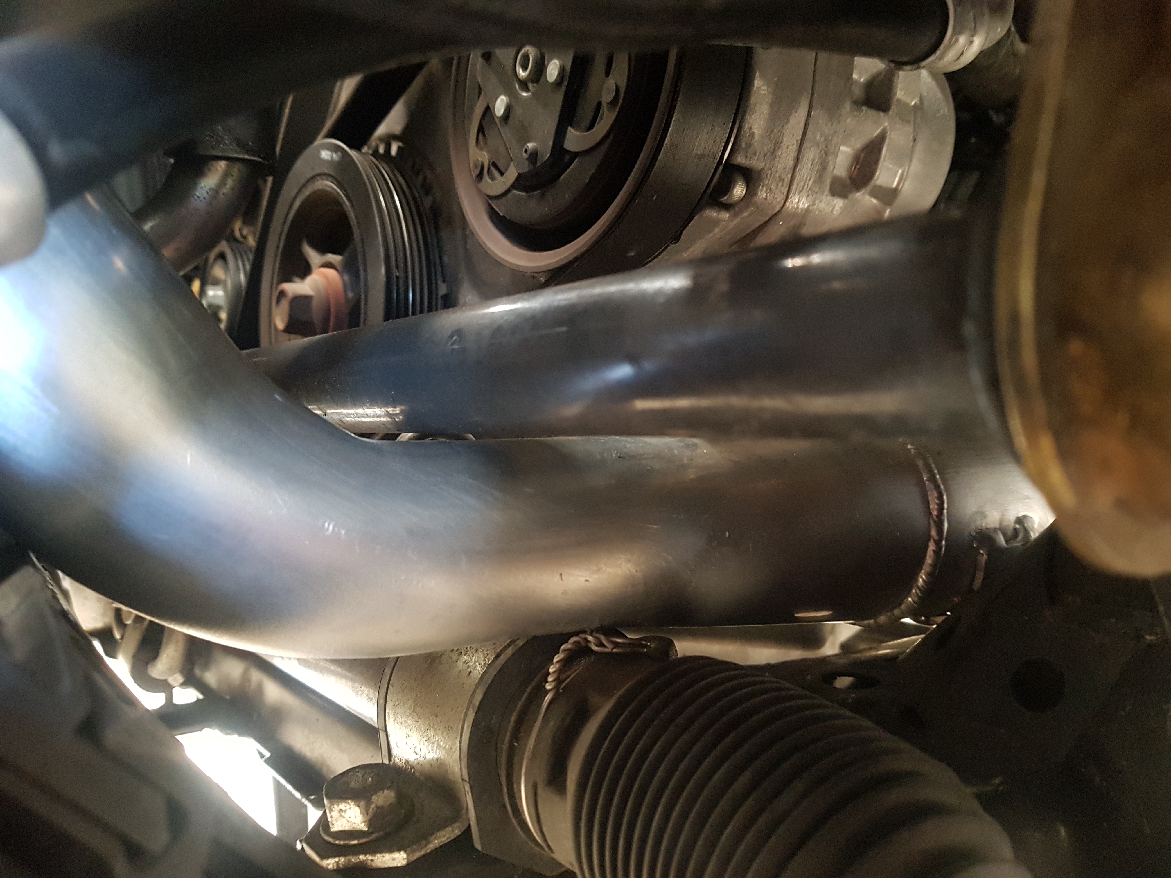
The next issue was squeezing between the front anti-roll bar and steering rack. The tube needed to be crushed slightly again. Clearance is tight but sufficient.
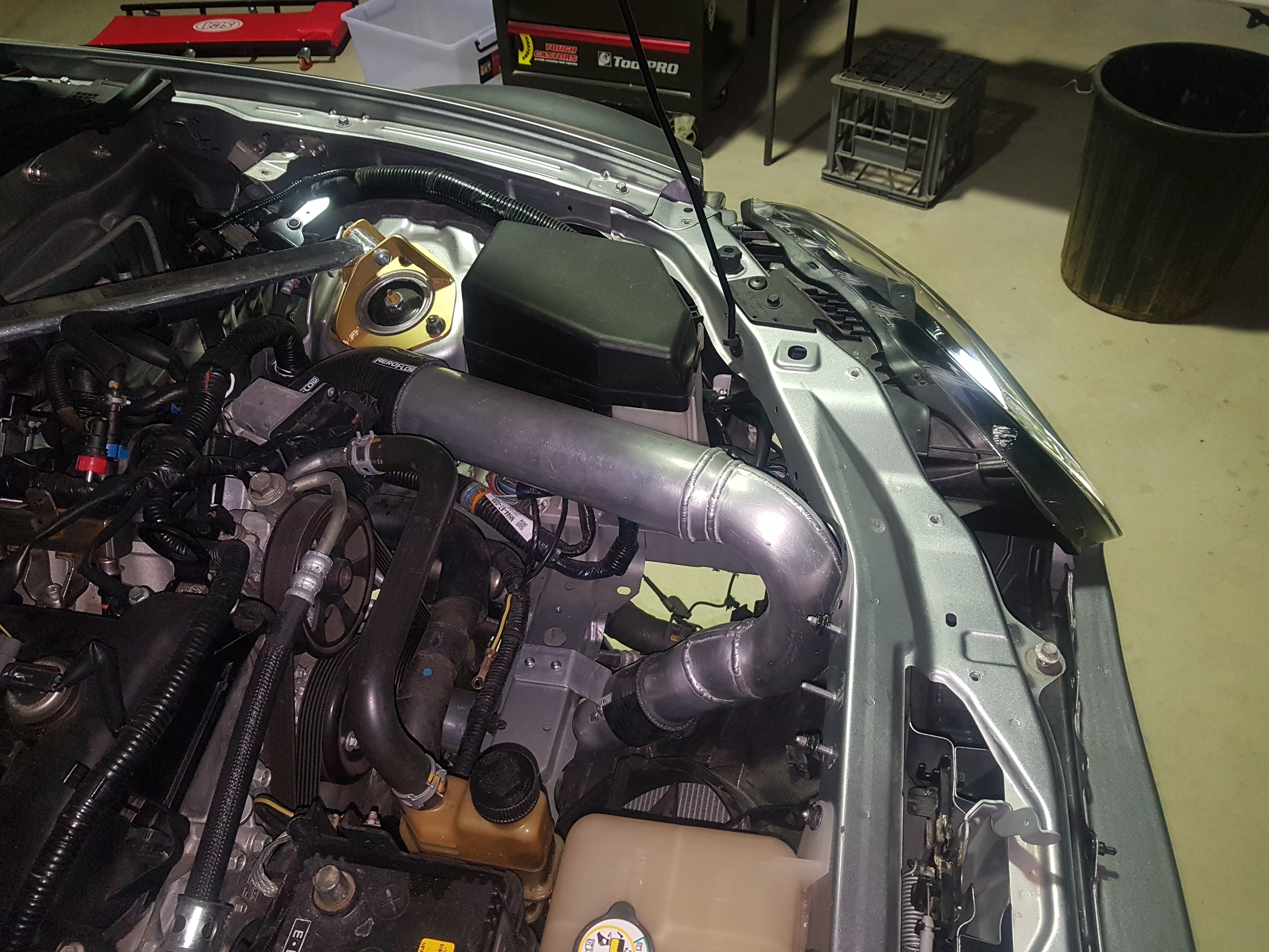
The final step was to bring the pipe up and rotate 180 degrees to connect to engine throttle body. After the rotation the tube size was increased form 2.5 inch to 3.0 inch. A Denso MAF flange was welded onto the 3.0 inch section and final connection to throttle body is made using a silicon 90 degree elbow.