I will be staying with the 2.0 MZR engine for the rebuild. It is a very popular conversion to put the 2.5 MZR engine in the NC MX-5. The problem with this for me is most of the increase in capacity of the 2.5 is from an increase in stroke.
MZR (Duratec) 2.0 bore x stoke = 87.5mm x 83.1mm
MZR (Duratec) 2.5 bore x stoke = 89.0mm x 100.0mm
In naturally aspirated form this makes sense as the increase in displacement and stroke gives a substantial increase in low and mid-range torque. The problem is that you cannot rev the 2.5 as high as the 2.0. I love RPM and with the electric supercharger low and mid-range torque is not an issue. The plan is to build a 2.0 with forged internals and up boost to 11psi and spin the engine to 8000rpm.
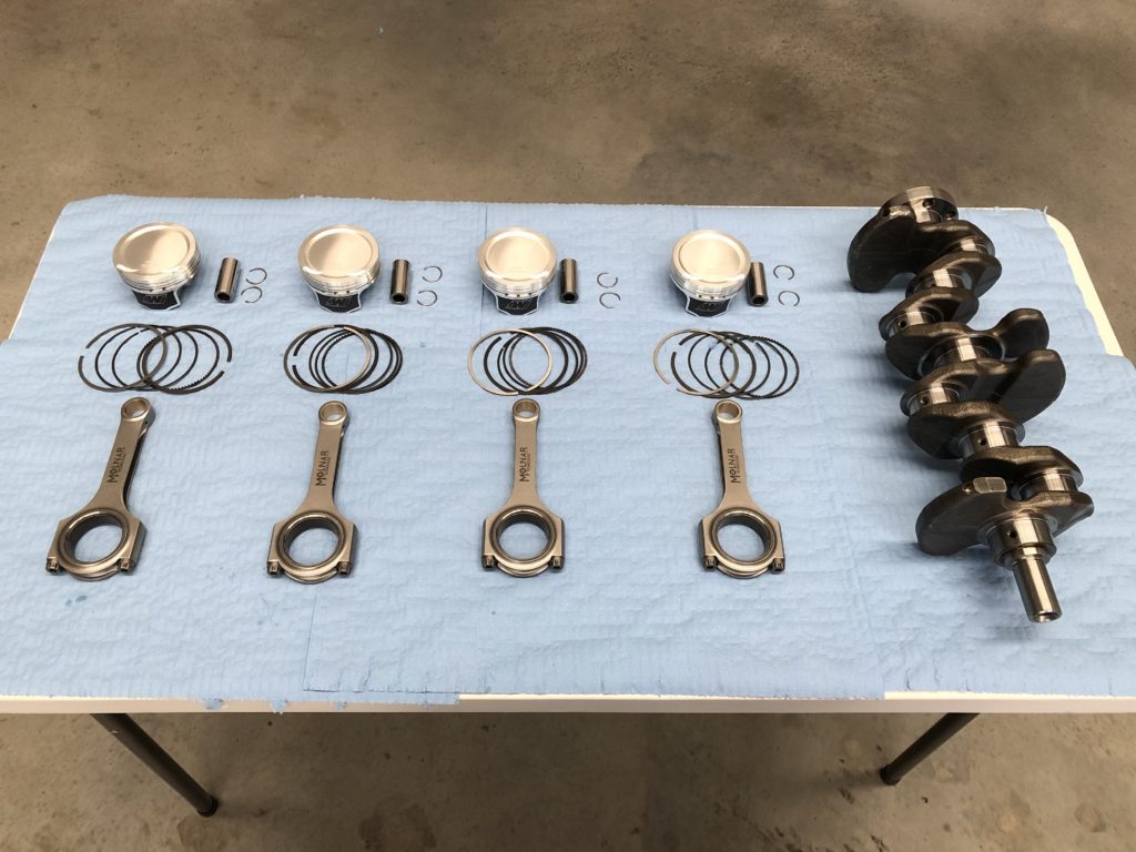
Build parts list:
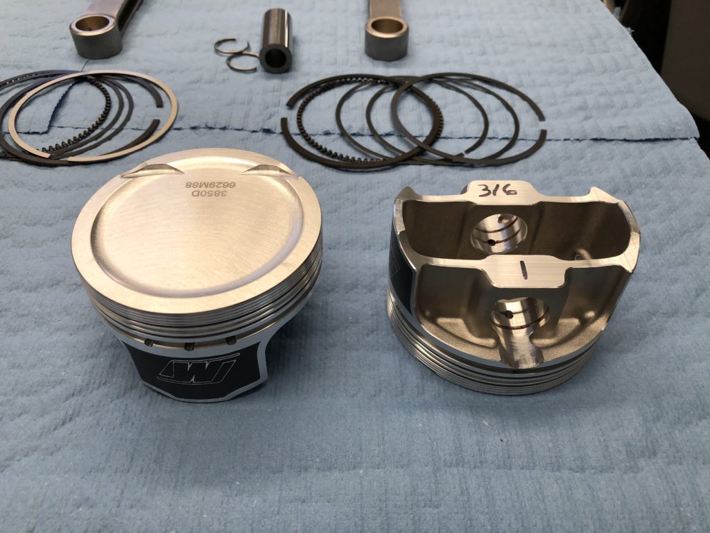
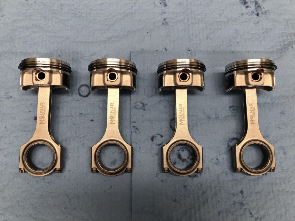
• Pistons – Wiseco forged 2618 alloy 88mm
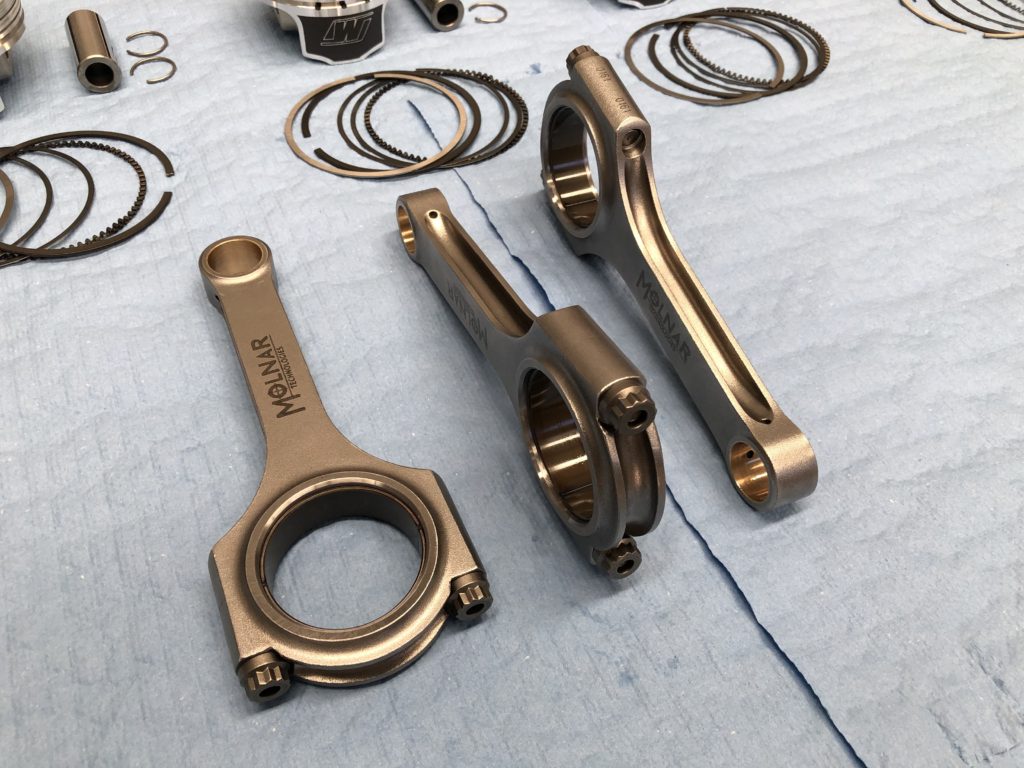
• Rods – Molnar forged 4340 steel h-beam with ARP2000 bolts
• Main bearings – King Racing
• Big end bearings – ACL Race Series
• Oil system – Raceline dry sump with Peterson 1.5 gallon oil tank
• Head gasket – Cometic MLS
• Main studs – ARP
• Head studs – ARP
• Front pulley bolt – ARP
• Cam sprocket bolts – ARP
• Cams – Xero Limit stage 1.5
• Valve Springs – Kelford Cams KVS17 Beehive
• All other gaskets and seals are Mazda OEM
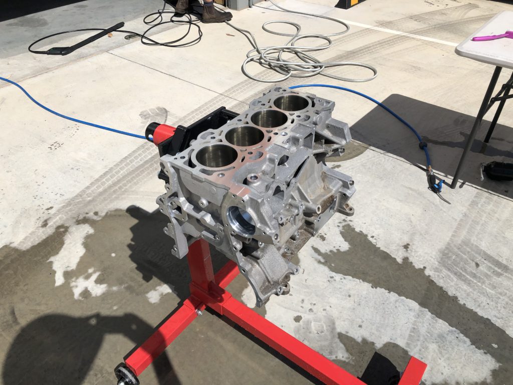
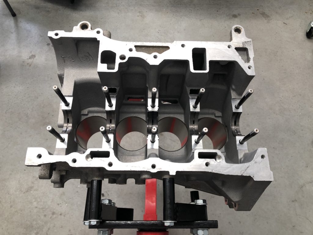
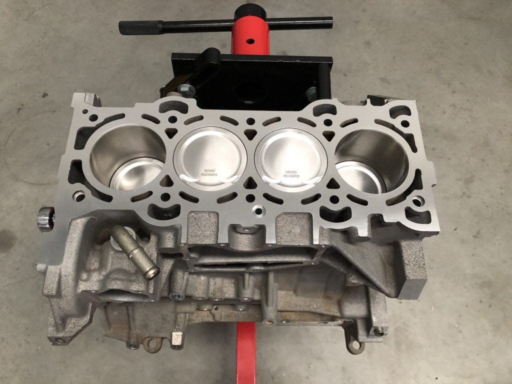
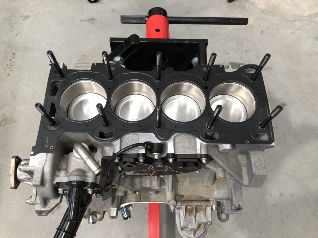
The forged 2.0 NC2 crank from the blown motor was taken to the shop for run out and crack testing. The crank tested ok so next a replacement MZR 2.0 engine was sourced and stripped for the block. Block was given to machine shop to be cleaned, bored and honed to 88mm, and decked.
After some consideration I decided to open up the engine clearance from the very tight OEM specs. Main bearing oil clearance set at 1.5 thou, big-end oil clearance set to 2.5 thou, piston to wall clearance set to 3.5 thou, and ring gap set to Wiseco’s “Circle Track” spec. All other specs as per OEM. Rotating assemble was balanced at machine shop.
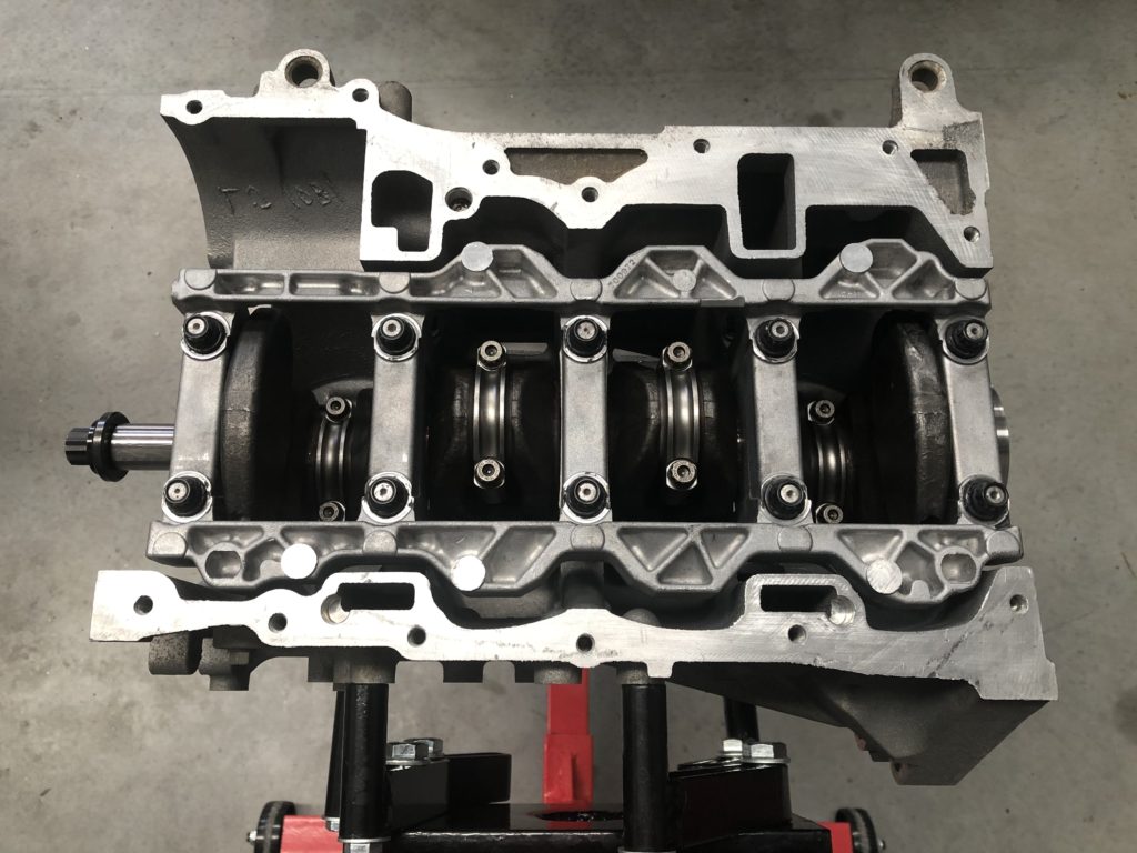
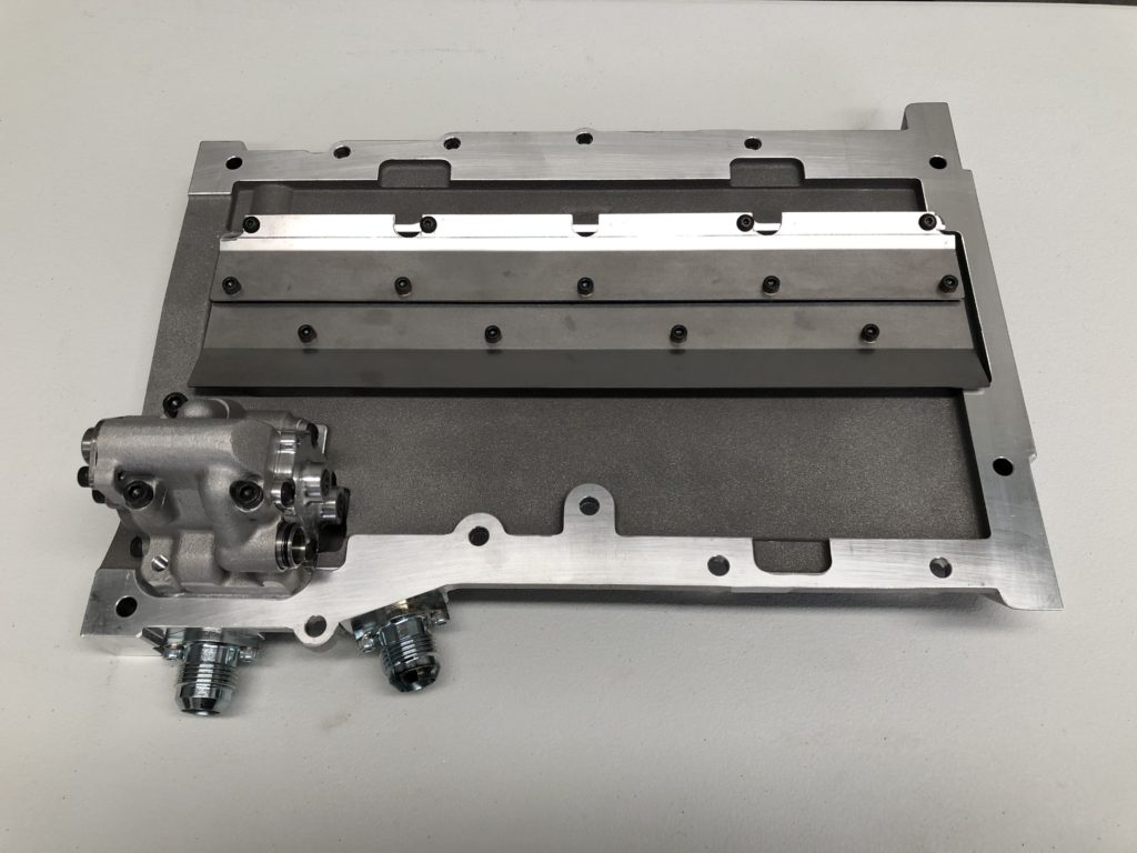
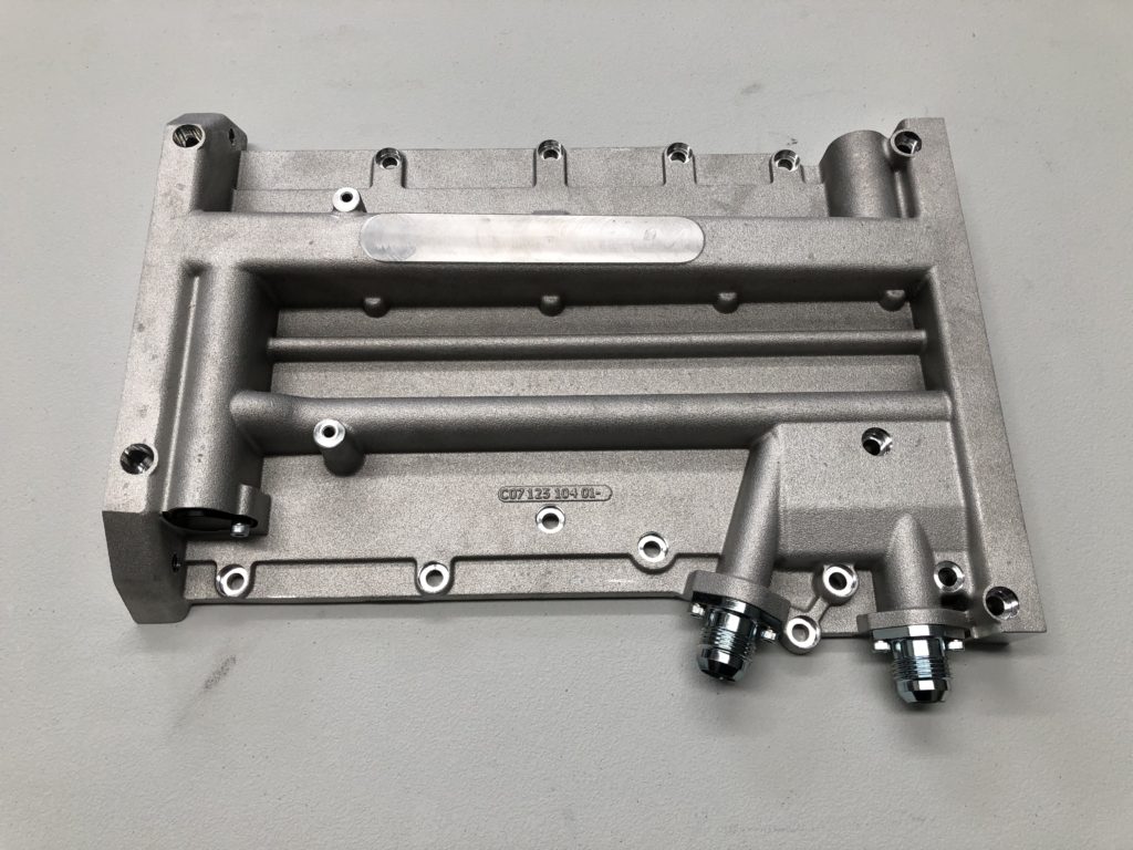
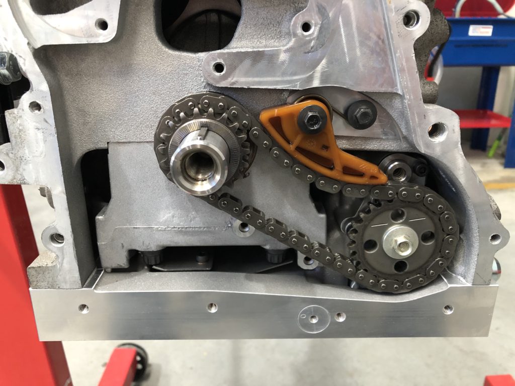
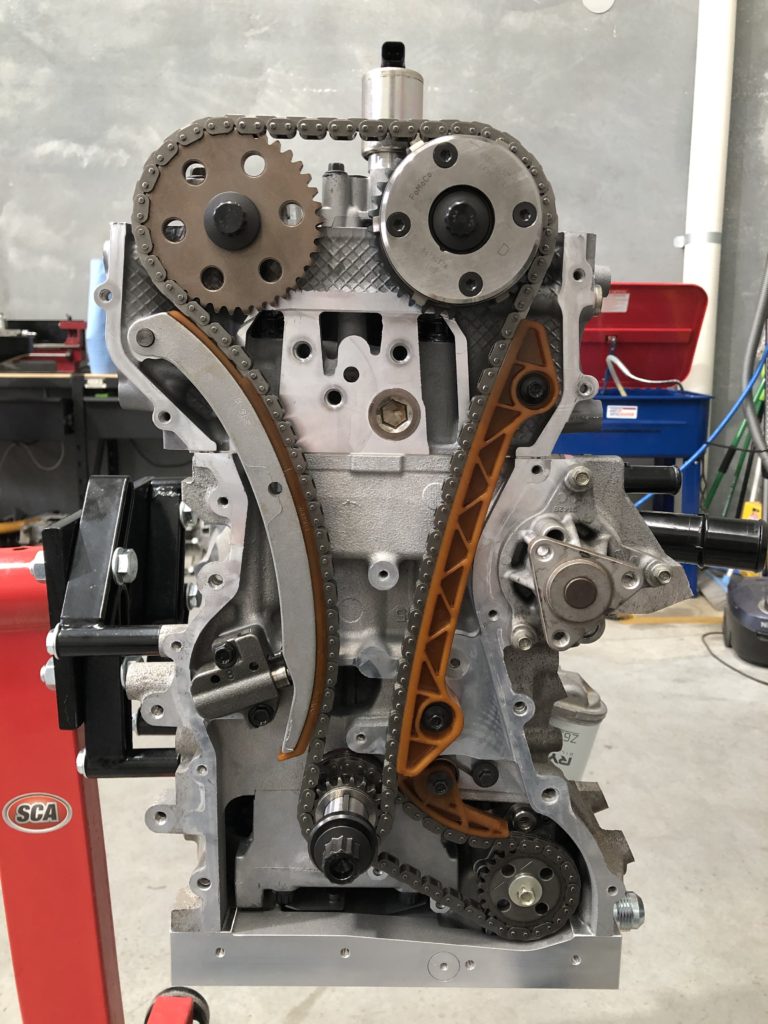
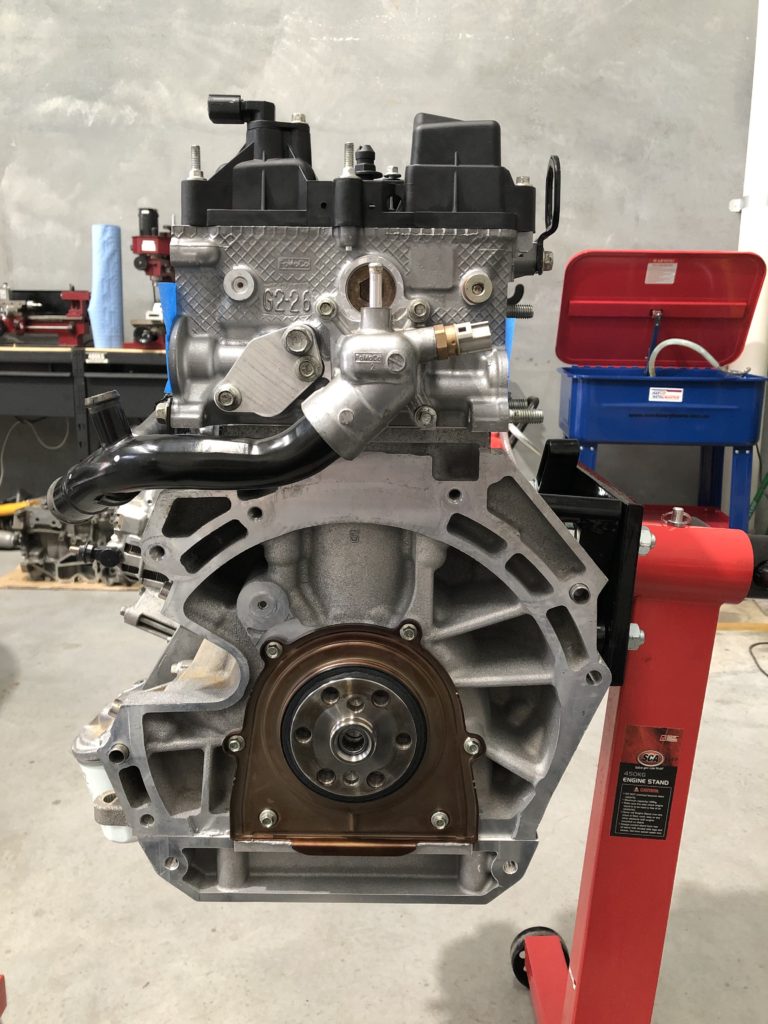
For the lubrication system I decided to upgrade the OEM wet sump system to the Raceline dry sump setup. This is a trick piece of engineering. It uses a single stage scavenge and single stage pressure pump which resides in the OEM location and uses the OEM chain drive so there is no external pumps, belts, etc. All that is needed is a external oil tank. This sump has a very low profile and the ARP main stud nuts extend further down than the factory main bolts and fouled on the sump. Some notches had to be cut into the windage trays to make it fit.
The front shaft of the crank has had a 1/8″ keyway cut into it along with the oil pump / cam timing sprocket and the front pulley. This is a insurance policy against any issues with the OEM friction retention setup.
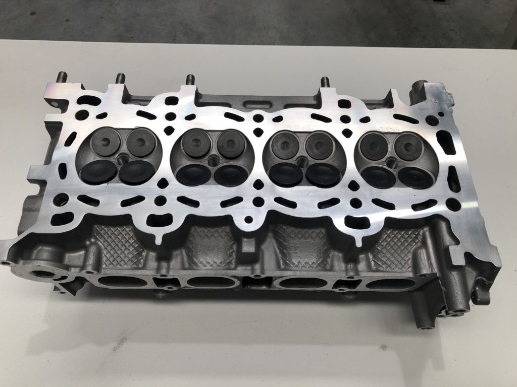
The cylinder head was given to the machine shop for a full recondition. All four valves on cylinder 4 were replaced with new items. All valve stem seals were replaced and valves seats recut. Upgraded cams and valve springs were installed, bucket tappets re-shimmed, and head was faced.
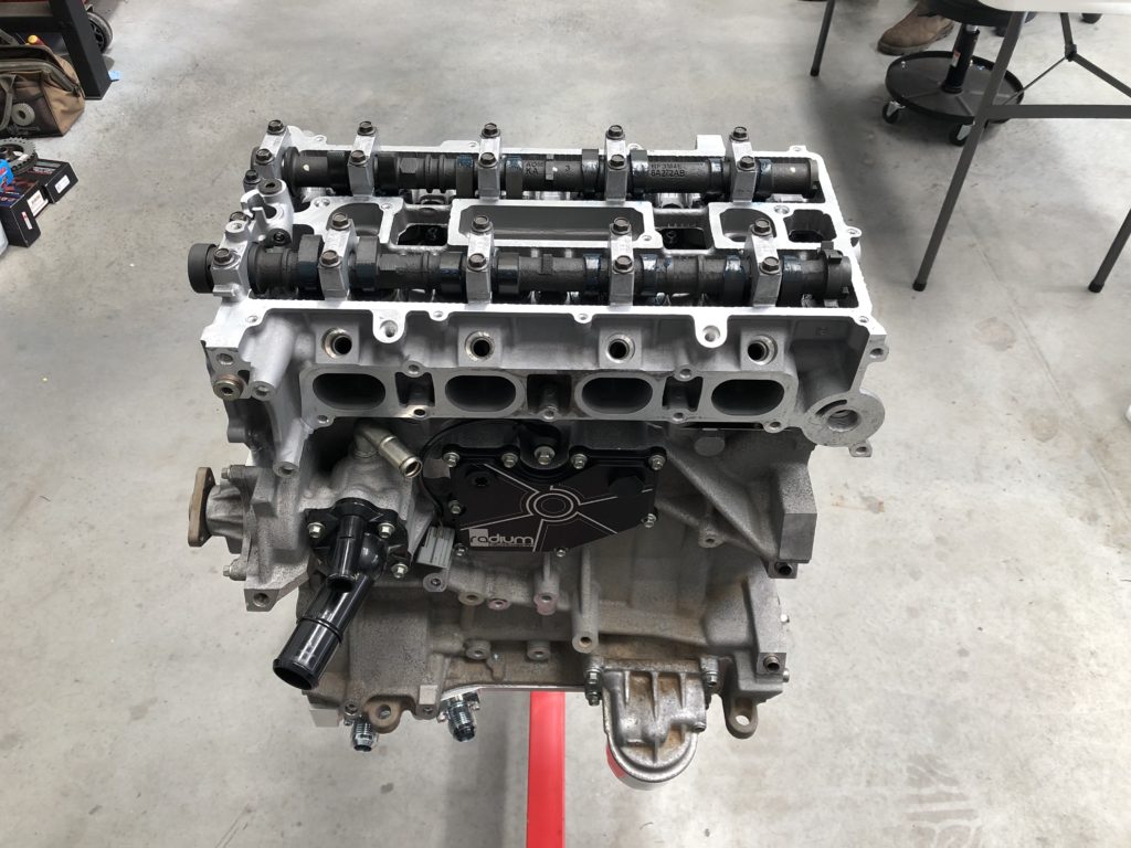
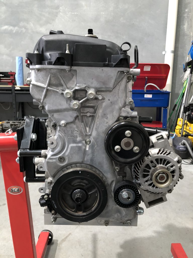
The air conditioning compressor has been deleted. This has allowed the alternator to be relocated to the other side of the motor to get it away from the hot exhaust manifold. The replacement alternator was sourced from a Mazda 3.
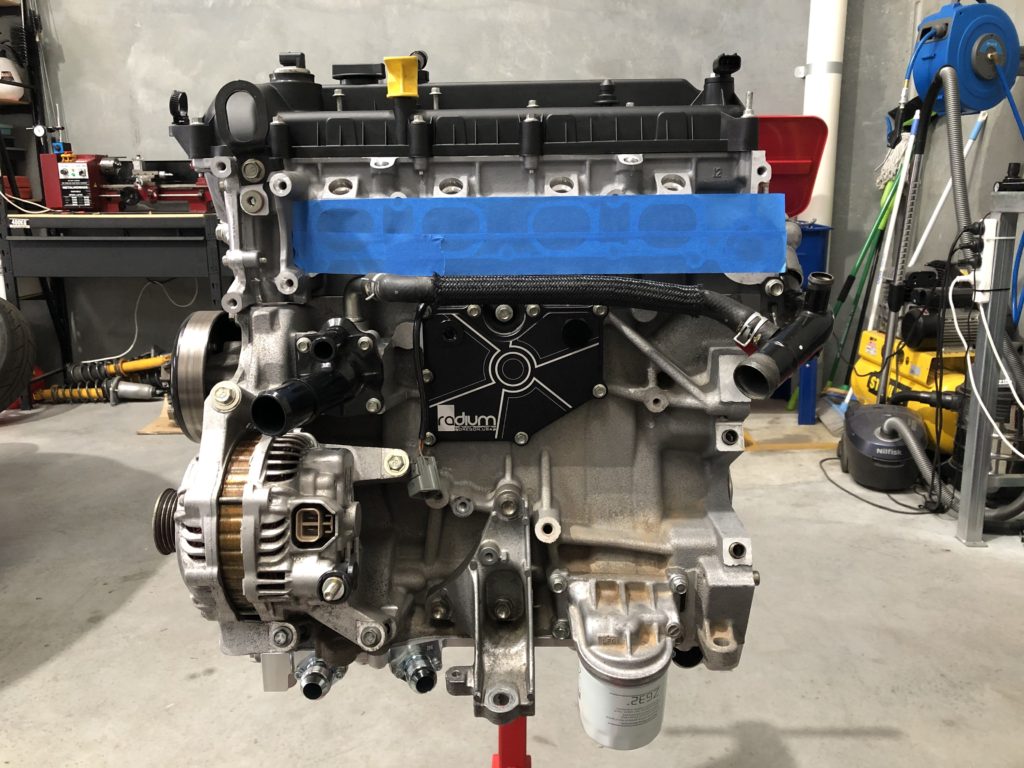
The factory oil separator and crankcase ventilation valve have been blanked off. The crankcase will breather out of the cylinder head cover into a catch can oil separator.
The exhaust gas recirculation valve has been deleted and blanked off on rear of cylinder head.
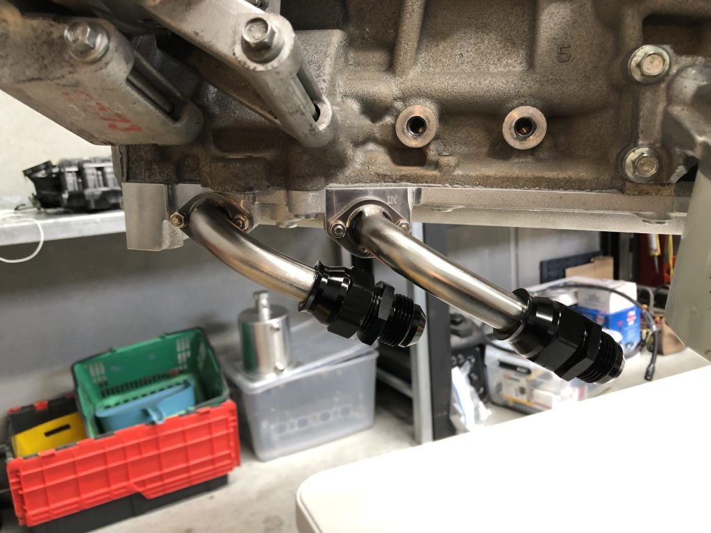
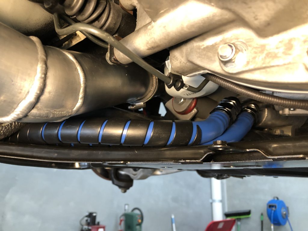
With the motor complete it was test fitted to engine bay to determine location of dry sump oil tank and routing of oil lines. The engine bay is too crowded to house the the oil tank so it will live in the passenger seat footwell. It also became evident that routing of oil lines would not be easy due to the charge pipe for the supercharger running down the left hand side of the motor.
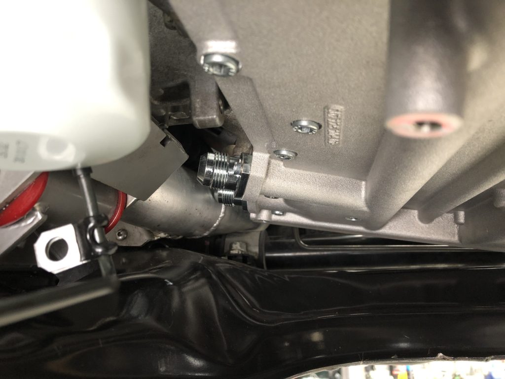
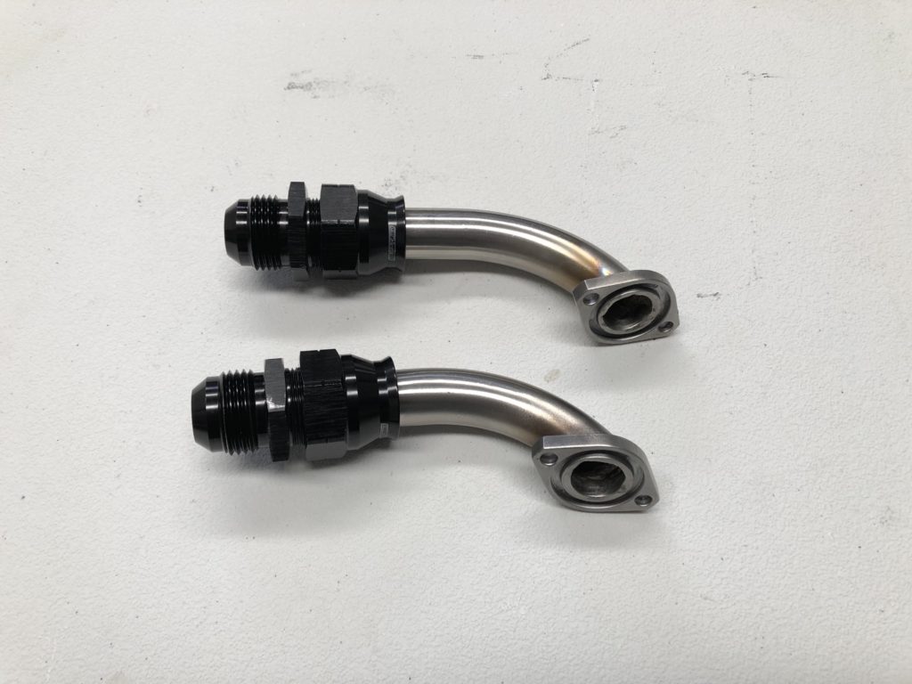
Even the tightest radius AN fitting would not clear and there is no other path the charge pipe can take. To solve this problem we decided to make tight radius 90 degree hard lines to connect directly to the sump then change from hard line to hose. The flange was cut off the AN fittings supplied with the Raceline sump and 3/4 inch 316 stainless steel tube was welded to the flanges.
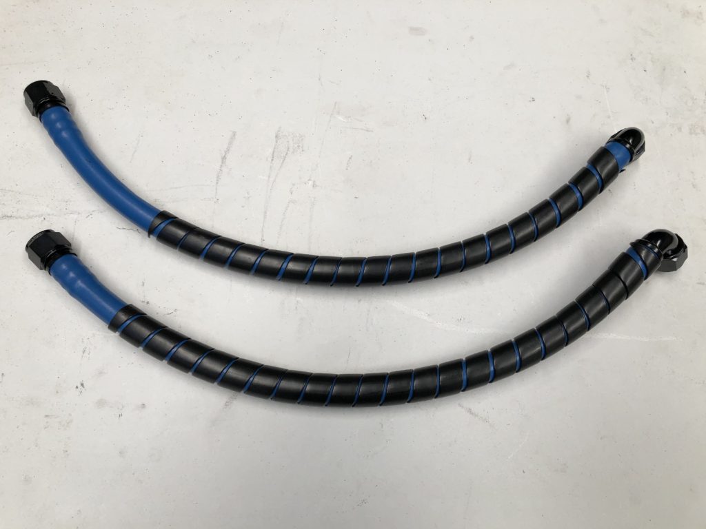
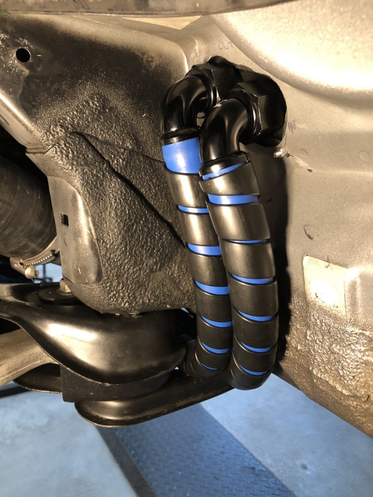
The original plan was to use stainless steel braided PTFE hose for all oil lines. A problem was encountered as this hose wants to kink with anything more than a slight bending radius. The path to get from the sump to the firewall is tight so for this section we changed to high temp (150 degC) AN12 Parker PKR rubber push-lok hose.
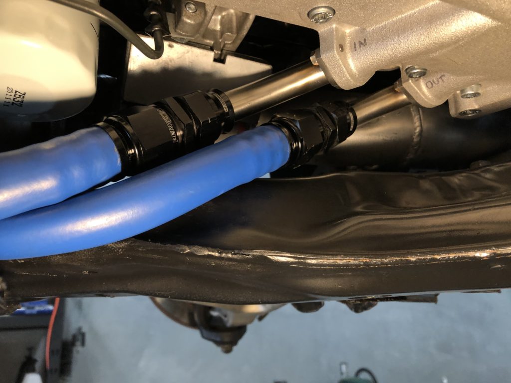
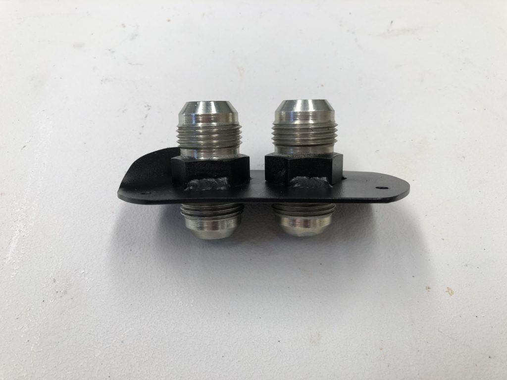
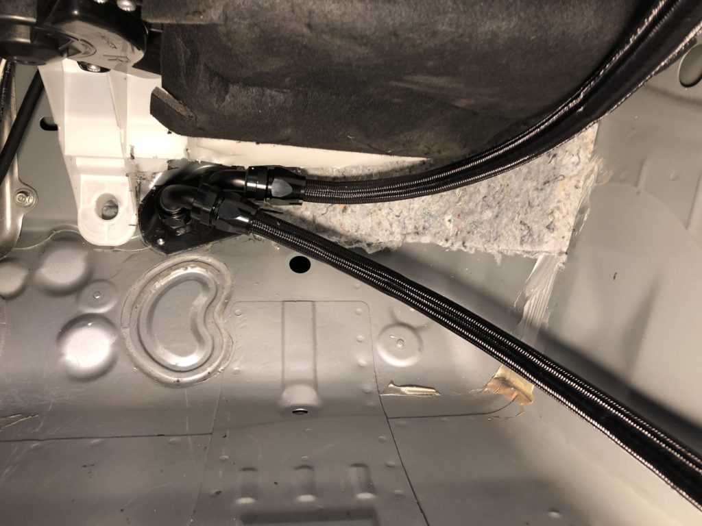
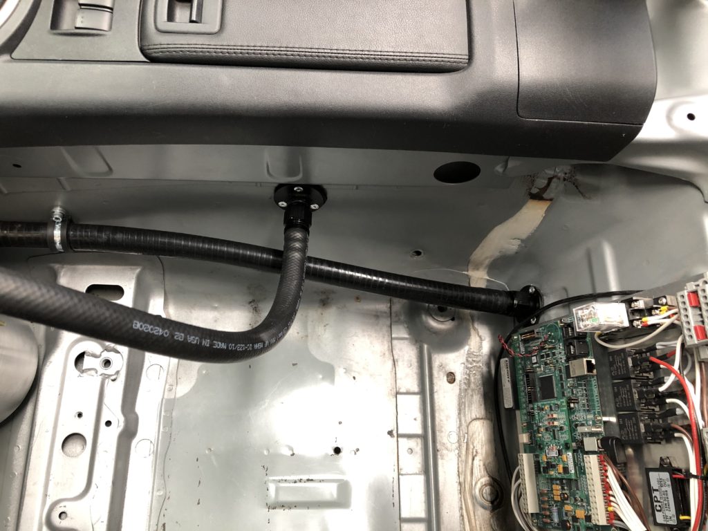
The hoses transits through the firewall from the left front wheel well into the passenger foot well. A bulkhead fitting was fabricated out of two AN12 unions.
Stainless steel braided PTFE AN12 hose was used for oil lines inside the vehicle.
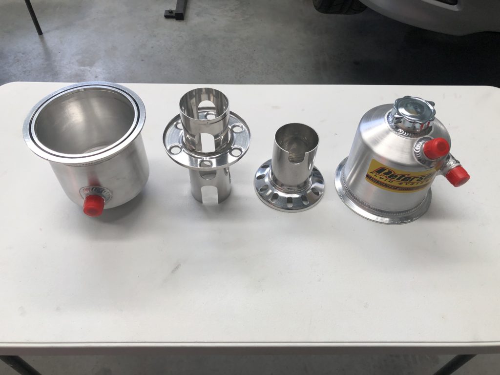
For the oil tank a Peterson 1.5 gallon tank was selected. The tank has internal baffling for the deaeration of the scavenge oil and maintains a tall column of oil over the pickup. It can be split in two with the two halves held together with a v-clamp.

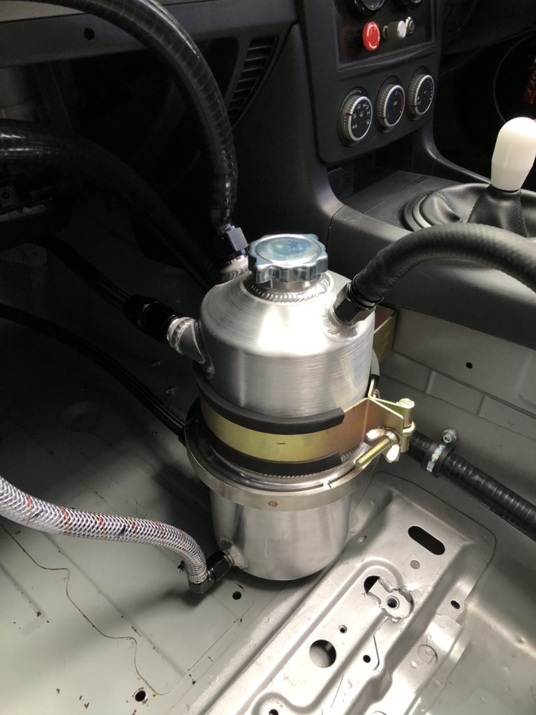
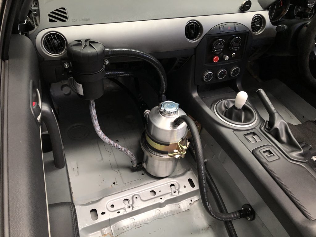
A additional AN8 and AN10 male fitting were welded to the oil tank for the breather system. The engine breathes out of the head into the top of the oil tank. The oil tank breathes into a Mann & Hummel Provent 200 air/oil separator. Any oil that accumulates in the separator is returned to the tank via a clear 1/2″ hose that doubles as a tank level sight gauge.
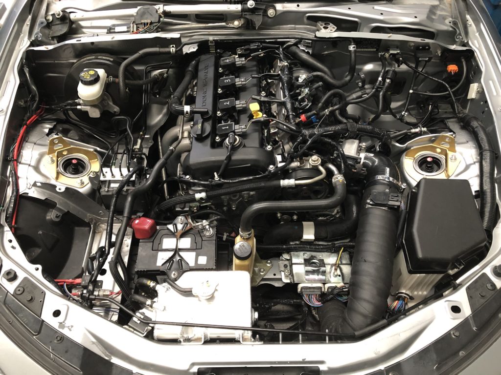
Finally the wiring harness was reconnected to the engine along with fuel, coolant, and vacuum lines. All fluids were filled. For initial break in a quality SAE 30 mineral oil was used with half a bottle of Red Line break-in additive to add some ZDDP to the mix. Engine was cranked with injectors isolated and spark plugs removed to prime oil pump. Spark plugs were installed and engine fired first crank and was run at approx. 2500 rpm for 20 minutes to break in the cams. Next it was taken out on the road and over 150 km of driving the load, rpm, and boost were gradually increased to bed in the piston rings.
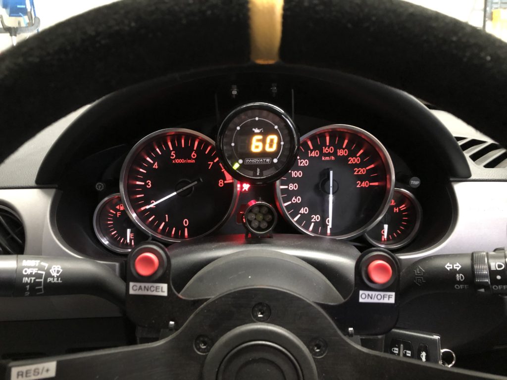
Following the break-in the oil was dropped and the oil filter was cut open to inspect filter medium with no surprises found. Oil tank was refilled with Mobil 1 0w-40. To monitor oil pressure and temperature on the new motor a Innovate Motorsport MTX-D dual function gauge was installed in the instrument cluster. With engine at operating oil temp, oil pressure is 30 psi at idle, and 60 psi from 3000 rpm to redline.