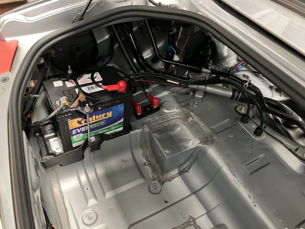
Part of the major upgrade is to increase the battery capacity 50% from 20Ah to 30Ah. This is being done to increase run time and also reduce volt droop at high current draw. The increase in capacity and size means the battery will no longer fit in the boot of the car so it will be relocated to the passenger seat well. This will also move the battery mass lower in the car and closer to the center of mass.
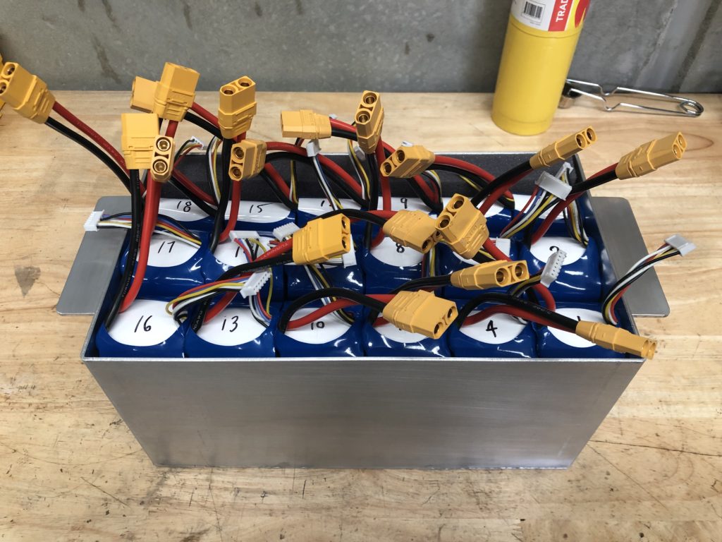
New 63V 30Ah battery and battery box
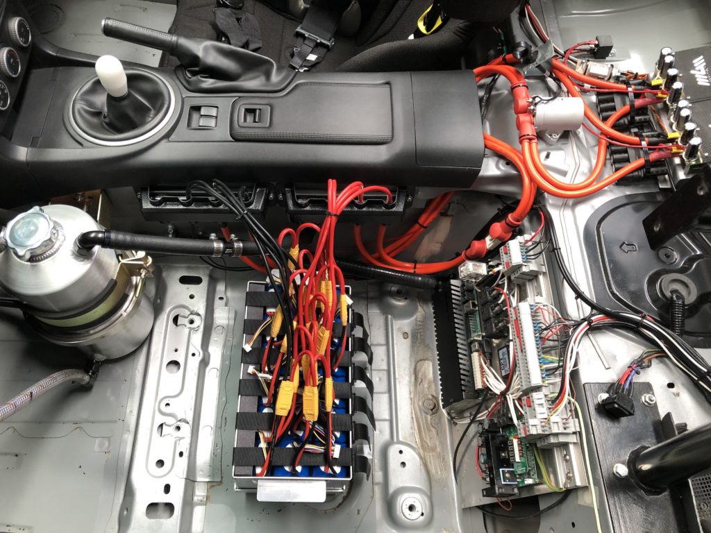
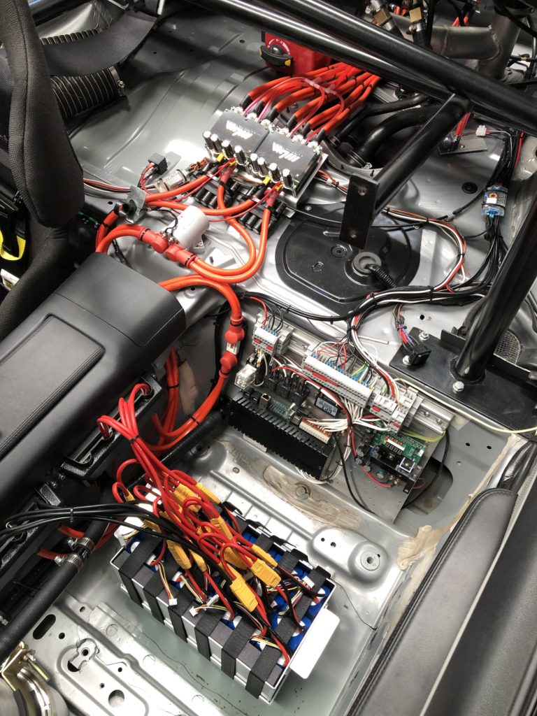
As the battery parallel string count has increased it has become difficult to manage all the electrical connections so a busbar arrangement for the main DC bus has been implemented. Cable size from each battery spring to the bus is 10mm2.
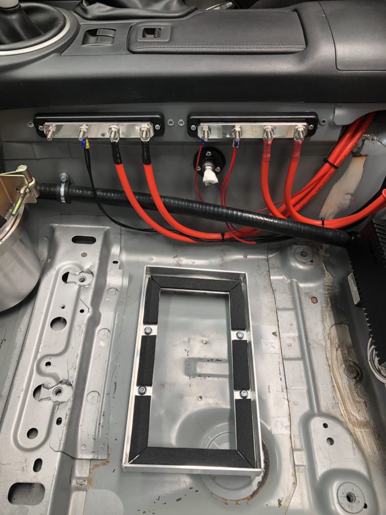
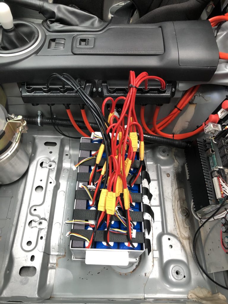
Battery tray and positive and negative busbarsBattery installed
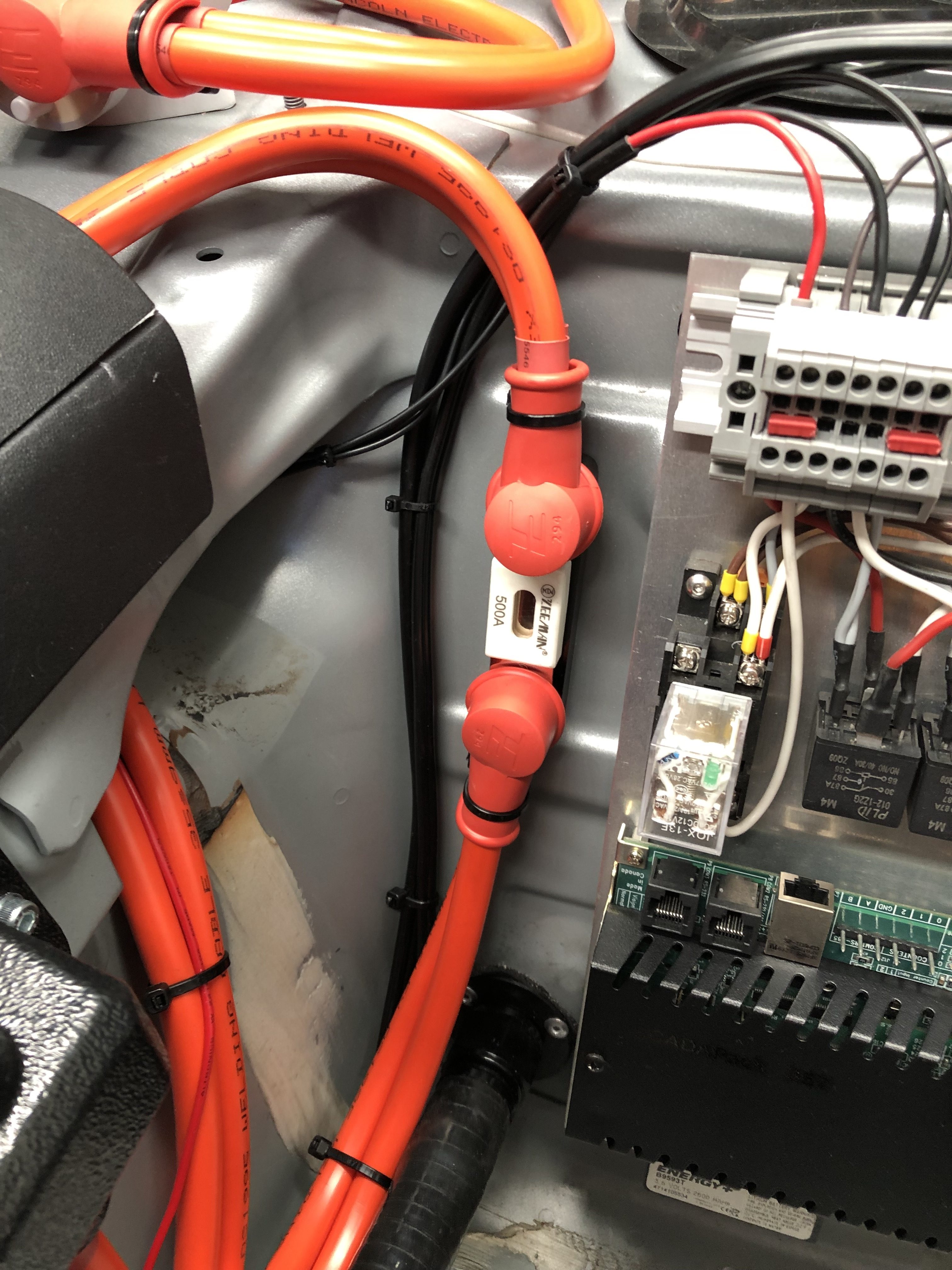
From the main DC bus to the ESCs, cable size has been increased to 35mm2 per ESC. For protection a new 500A fuse has been installed and the 500A DC contactor has been carried over.
500A fuse500A DC contactor
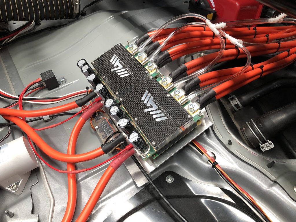
The ESCs have also been relocated to sit in between the battery and electric motors and are now mounted side by side.
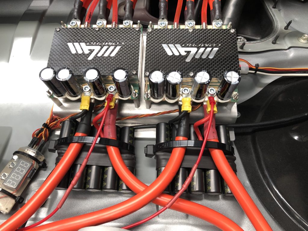
ESCs on new mount and with upgrade cables
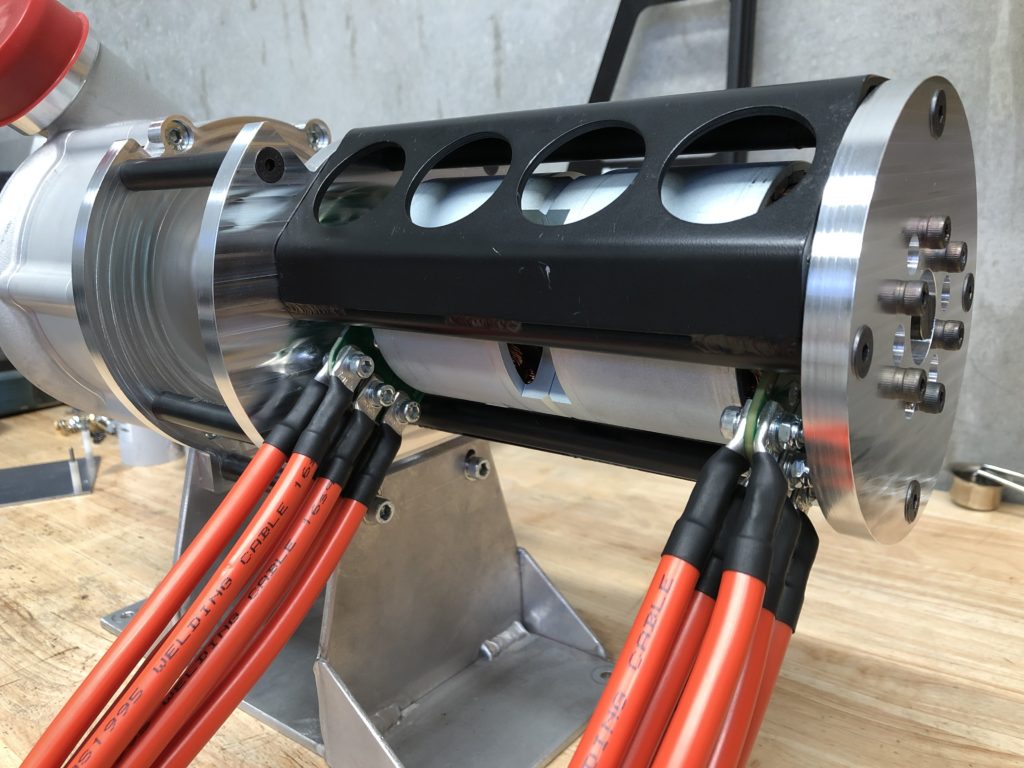
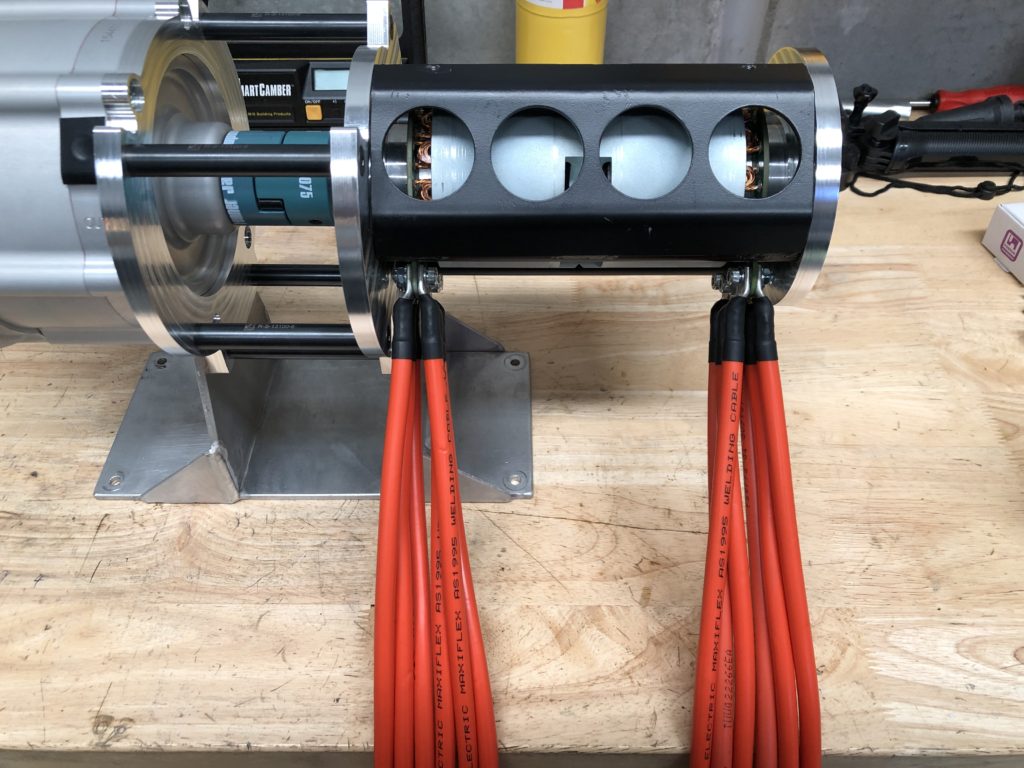
From ESCs to each motor phase, cable size has been increased to dual 16mm2 (total 32mm2) per phase.
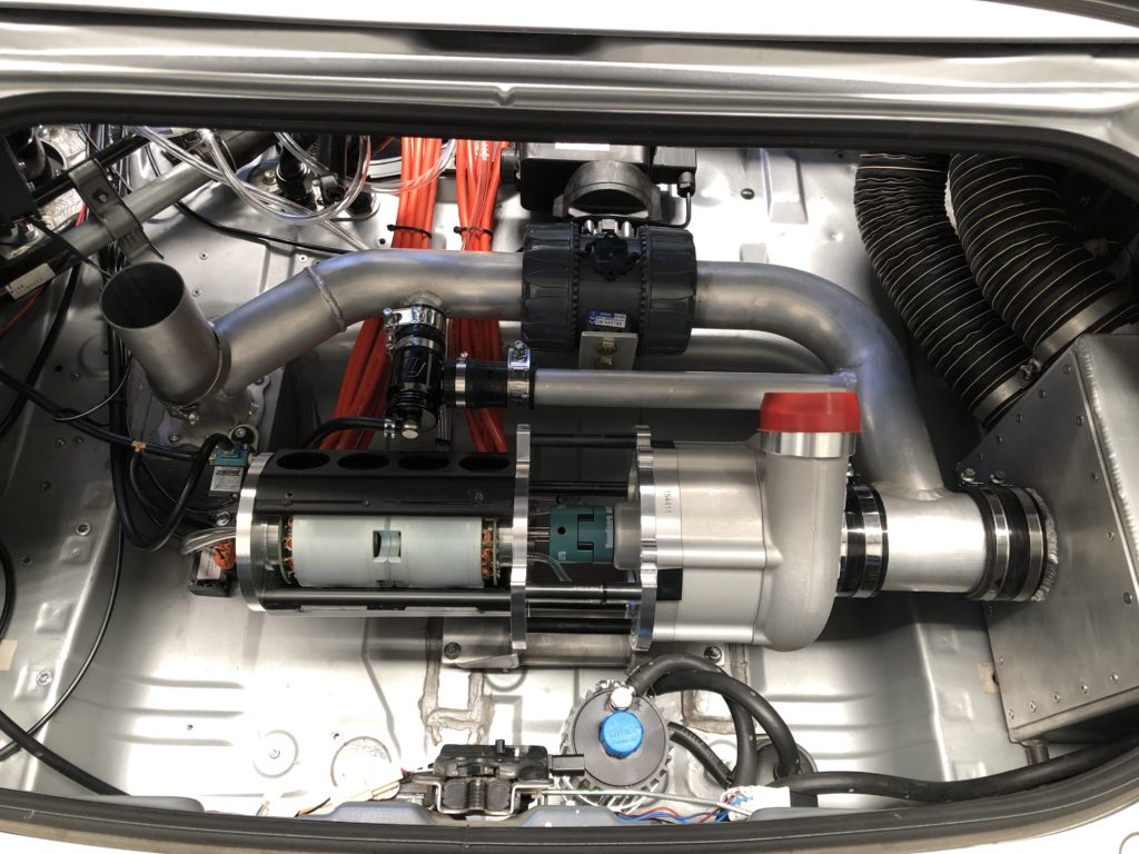
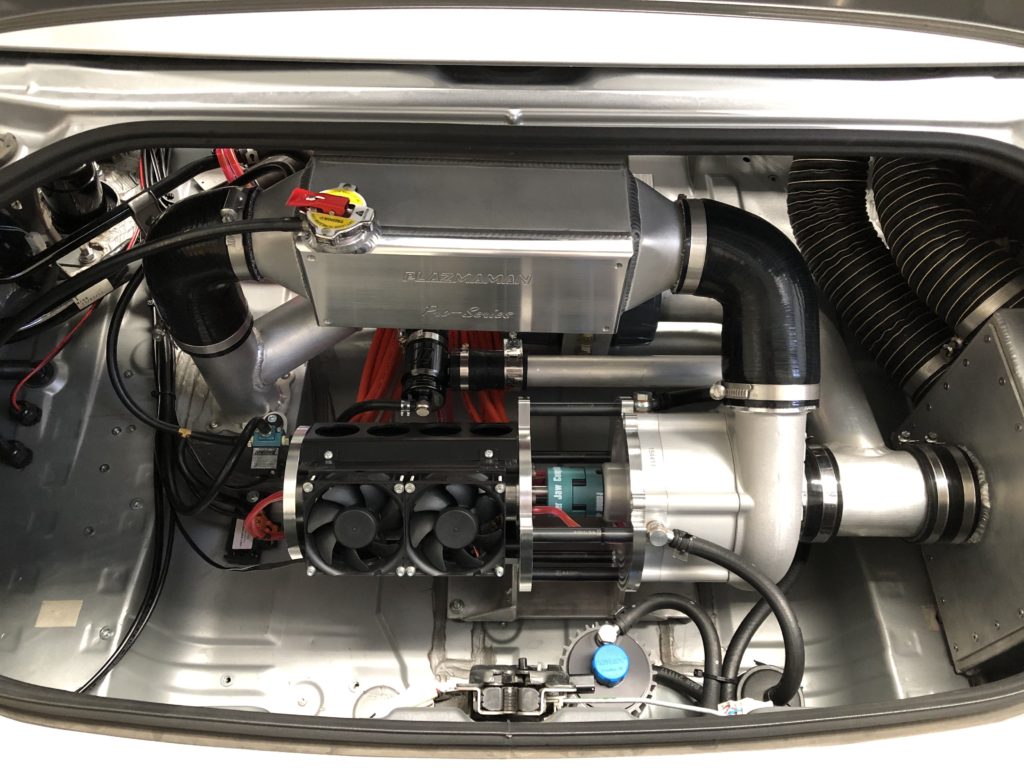
Electric motor phase cablesElectric motor phase cablesUpgrade electric supercharger unit back in car
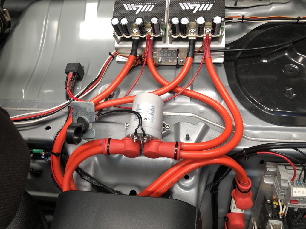
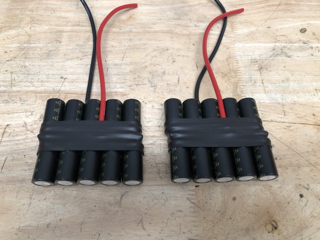
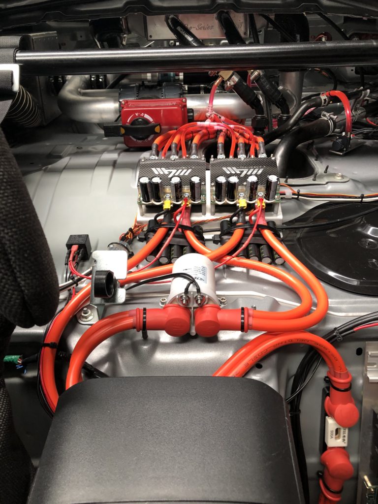
The inductance of the cables between the battery and electronic speed controllers has increased due to the increase in both cable length and cross sectional area. To deal with this, two 10,000 uF capacitor banks were assembled using low ESR electrolytic capacitors. These were wired to to the input terminals of the electronic speed controller.
It’s been a while since my last update. I haven’t posted due changing jobs and lack of free time. The major upgrade has been a bit of a disappointment. I have not been able to reach the desired 11psi boost pressure at high engine RPM. I have managed to up the boost pressure to 10psi but only for short periods before the speed controllers’ trip on thermal overload. The below video shows what 10psi electric boost looks like but you will also see the system trip at the end of the run.
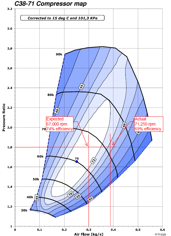
To try and explain the issue let’s take the following operating point:
Mass air flow = 0.3 kg/s (measured by the MAF sensor) at 7,500 rpm on the internal combustion engine
Pressure ratio = 1.8 (10 psi measured at the MAP sensor with a 2 PSI pressure drop across intercooler and charge pipe)
At this operating point the new compressor should be right on the middle of the efficiency island with impellor spinning at 67,000 rpm and the electric motors consuming 25.5 kW of electrical power (see below compressor map).
But looking at the data, in reality the impellor is spinning at 71,250 rpm and the electric motors consuming 36 kW of electrical power. The only way this makes sense at this pressure ratio is if the mass flow is much higher (closer to 0.39 kg/s) or the actual pressure at the outlet of the compressor is much higher. The higher power consumption means higher current and leading to thermal overload of ECS’s and electric motors.
So, the question is what is going on? Below are potential causes and corresponding fault finding conducted:
Boost leak between compressor and engine – thorough leak test of pipework conducted with no leaks of consequence found
Higher than expected differential pressure across intercooler – differential pressure measured and found to be as expected (~2 psi)
Manifold air pressure reading incorrect – reading has been confirmed against another sensor
Compressor recycling – recirc valve was removed and capped, not change
Lower than atmospheric pressure at compressor inlet – inlet pressure measured with vacuum gauge and no issue found
So, I am at a loss. I contacted Rotrex support, and they recommended creating a warranty claim and send the C38-71 back to them for inspection.
So, after the disappointment of the bigger compressor have decided to accelerate the development to the next step. I know that I won’t get to my ultimate peak power goals with the electric supercharger on its own, and definitely not for prolonged track sessions. For the high end of the engine RPM range a turbo charger is always the best power adder as there is so much waste heat energy going out the exhaust.
The great thing about the electric supercharger system is the instant boost and the throttle response and control which is almost NA like. So, the plan is to put the smaller compressor back to create boost from idle to ~4500 rpm, then from 4500 rpm to redline the turbo will take over. In essence it will be an electric anti-lag system.
The electric system will be stripped out of the car entirely. A turbo will be installed and tunned, then the electric system will be reintroduced.
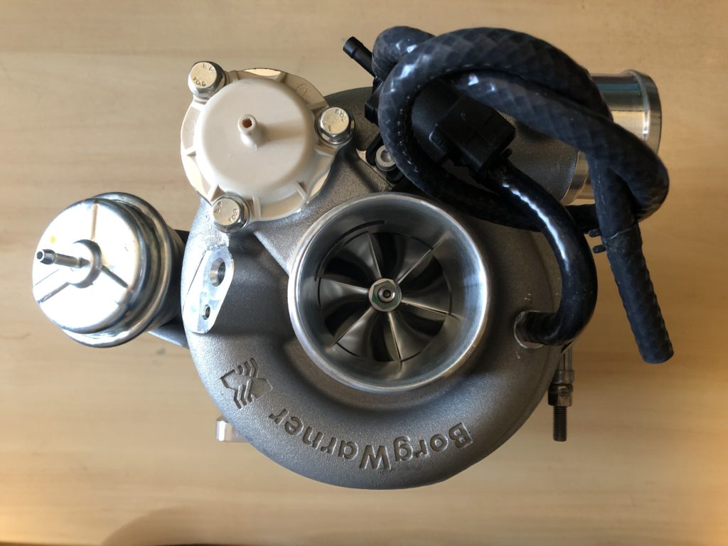
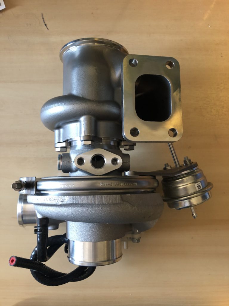
The turbo selected is the Borg Warner EFR6758 which is good for 500 HP. It was ordered with internally wastegated 0.85 A/R turbine housing, T25 turbine inlet, and v-band turbine outlet. It has ceramic ball bearings in an aluminium center housing so will need to be water cooled.
EFR6758EFR6758
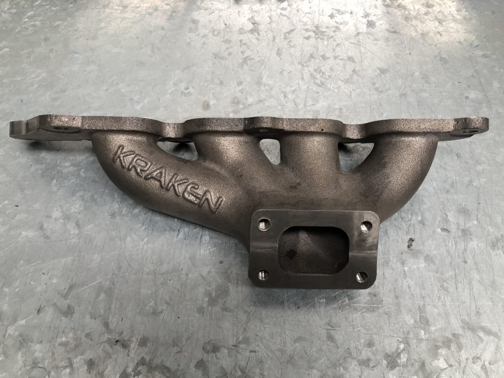
For the exhaust manifold options are limited. Low mount turbo manifolds don’t work on right hand drive MX-5s as the steering column goes right through where the turbo would sit. I wanted to go with a cast manifold, mainly for reliability so ordered a Kraken top mount manifold.
Kraken top mount exhaust manifold
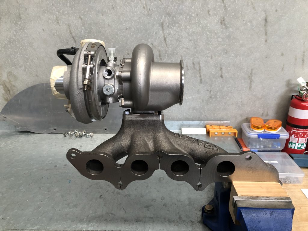
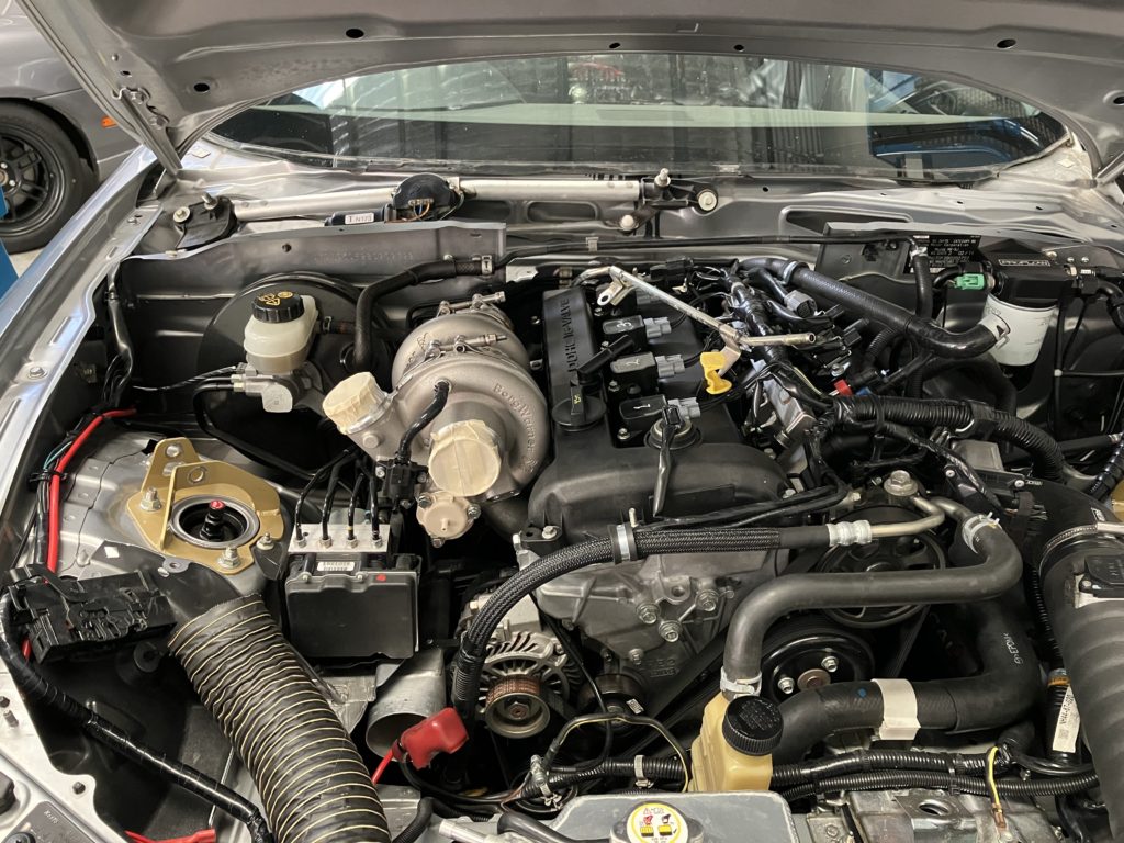
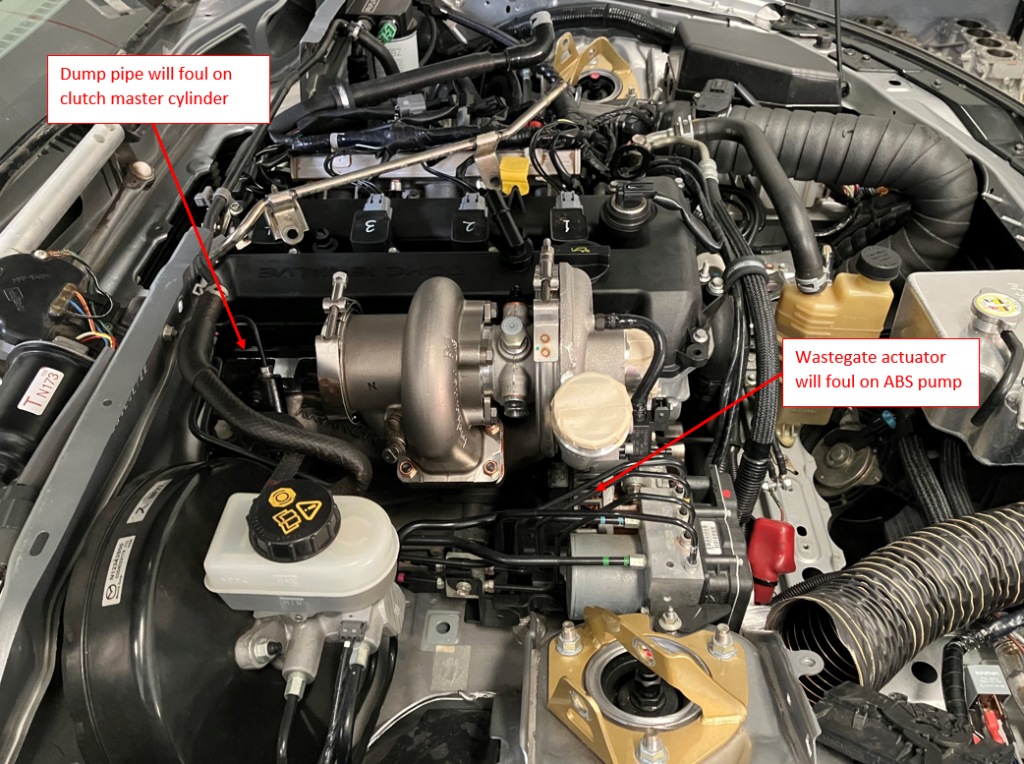
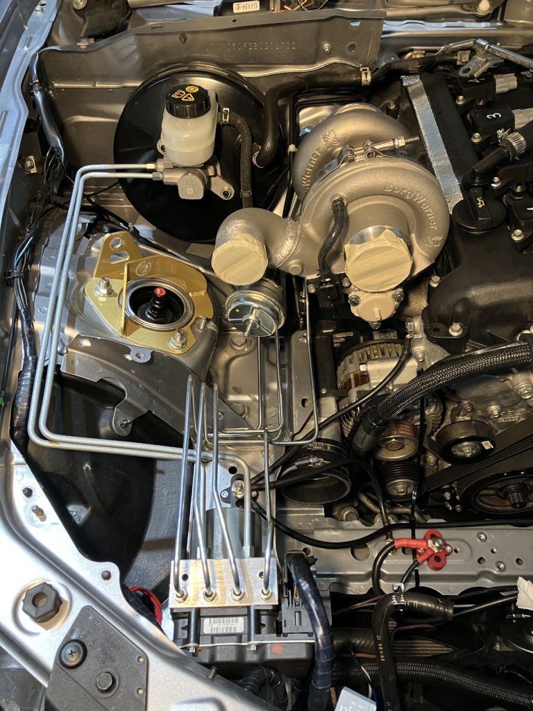
Turbo and manifold were mocked up to the engine to determine intercooler pipework routing and any clearance issues. Three issues became immediately obvious. First the turbo sits high in the engine bay and the comprosser outlet was fouling on the bonnet. Second the wastegate actuator and ABS pump want to occupy the same space. And the third was the clutch master cylinder is right where the dump pipe will be. The clutch master cylinder issue is another problem that presents in RHD drive turbo installs and not LHD.
Turbo on manifoldMocked up in carTwo issues to solveClutch master cylinder will have to be relocated
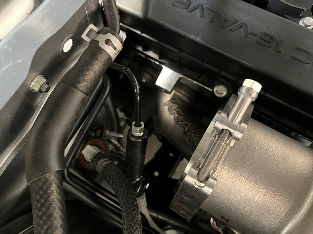
To solve the bonnet clearance issue a 2″ aluminium 90-degree elbow was welded directly to the compressor scroll. Also, the wastegate actuator mount was modified extended the wastegate actuator forward and allow the compressor housing the be counter clocked further clockwise.
90-degree compressor outlet and extended wastegate actuator mount
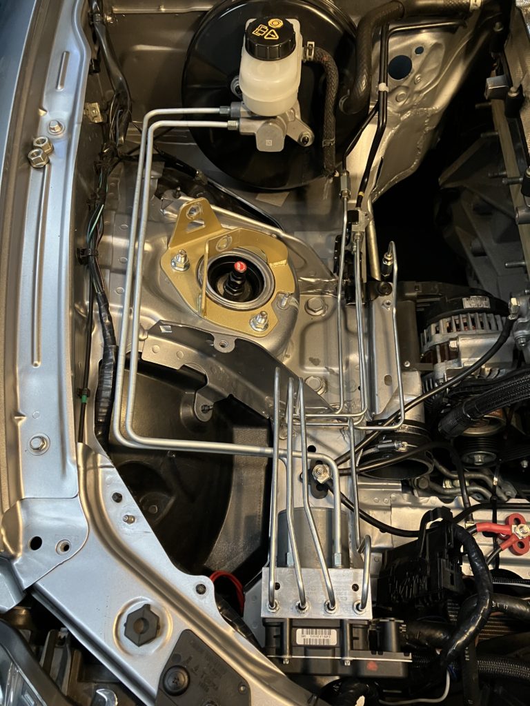
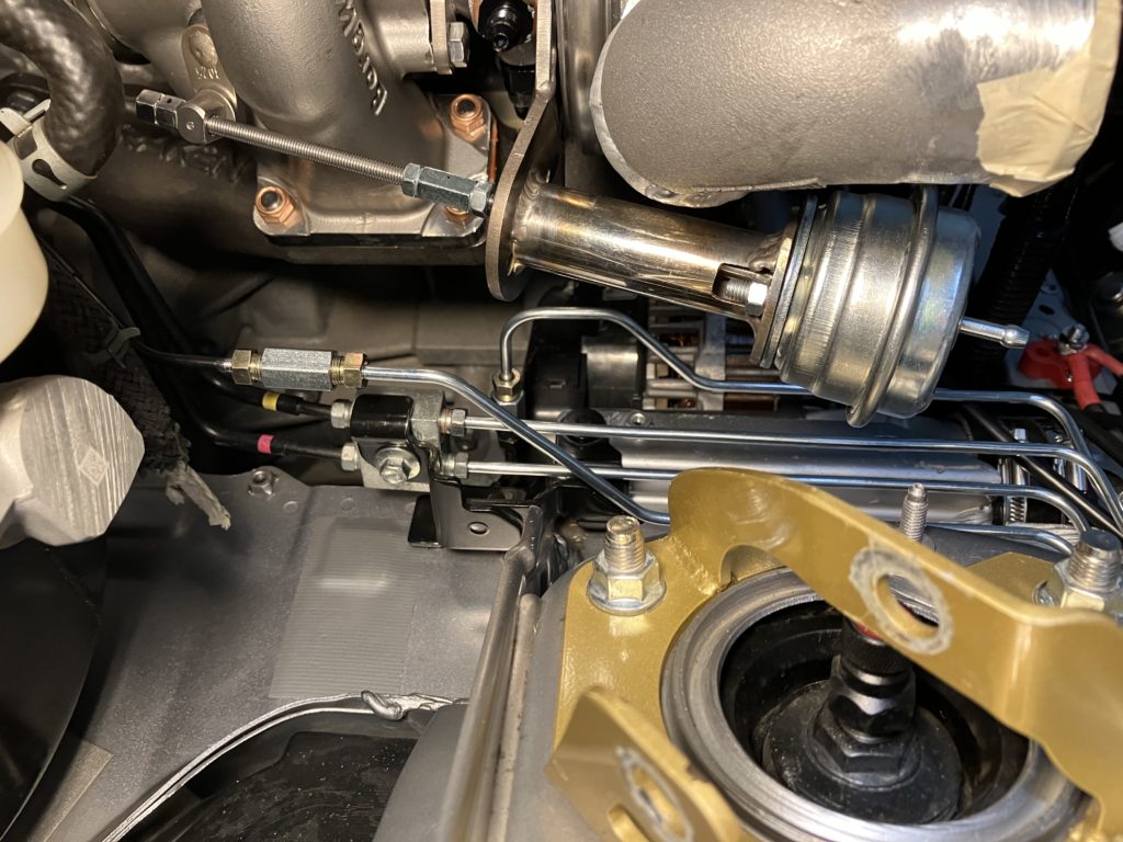
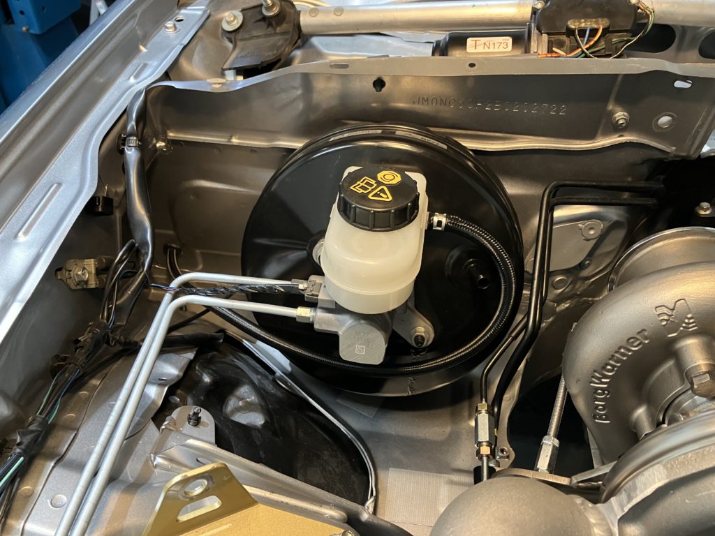
To solve the ABS pump clearance issue the pump was relocated as far forward on the chassis rail as possible. The two brake lines between the master cylinder and ABS pump were remade with 1/4″ double-walled bundy tube. The four lines from the ABS pump to each brake caliper were extended using 3/16″ double-walled bundy tube.
New brake linesNew brakes lines with turbo in placePlenty of space now
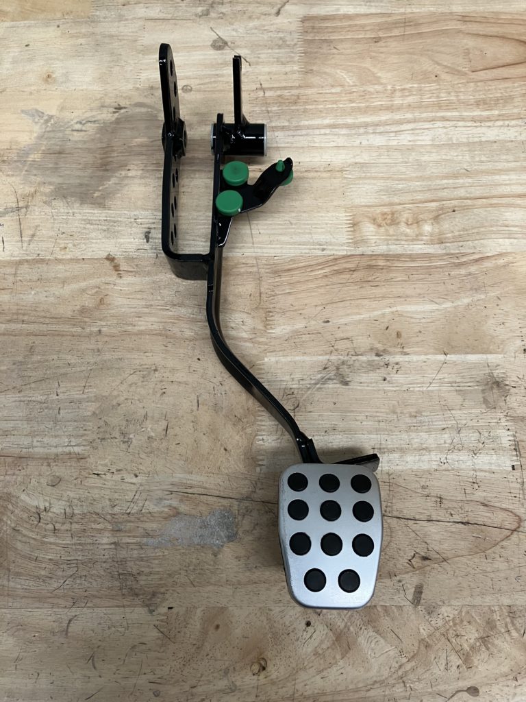
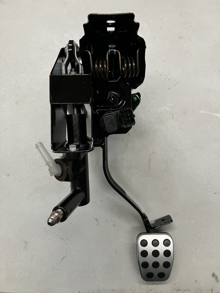
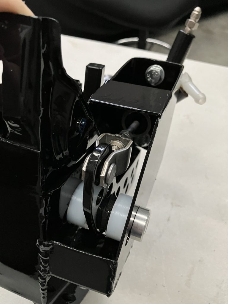
The final clearance issue was the most difficult to solve. The clutch master cylinder could not stay where it was. It was decided to move it inside the cabin. The clutch pedal assemble was removed from the car for modification. The pedal itself had second lever arm welded on. The pedal assemble was modified to mount the master cylinder to it. The whole assemble was reinforced as this is a week point on these cars.
Modified clutch pedal with second lever arm on left sideClutch pedal assembly with master cylinder attachedLever arm and master cylinder plunger
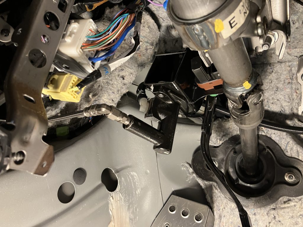
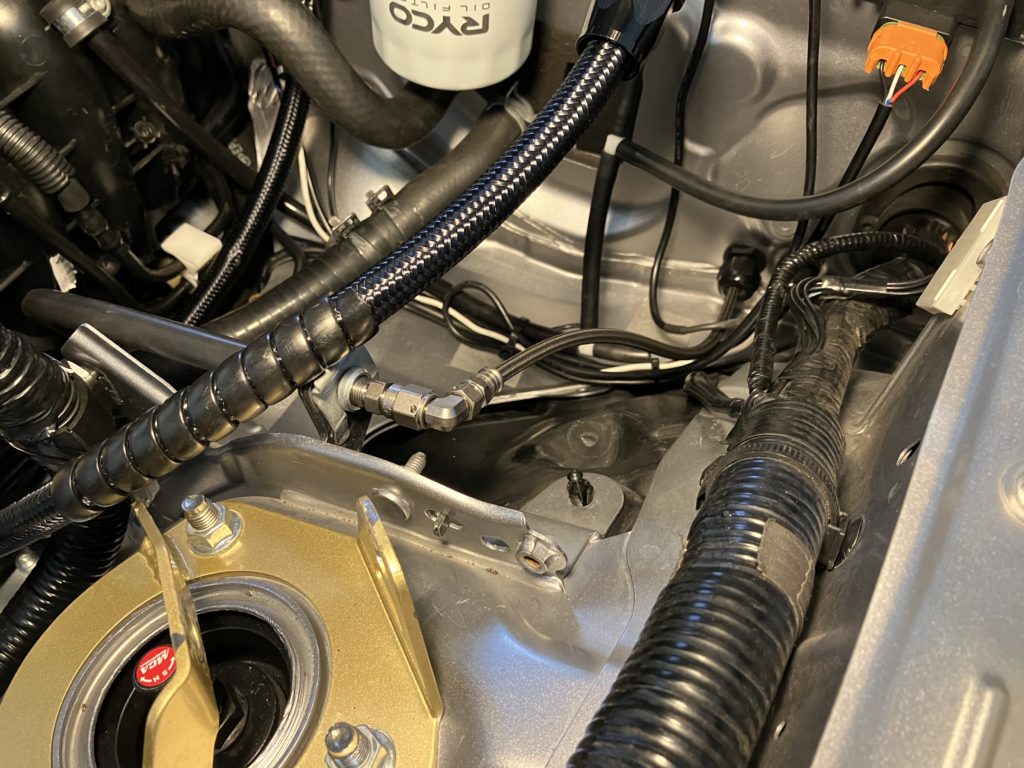
Low pressure hose was run from the brake fluid reservoir, through the firewall on the driver’s side, to the suction of the master cylinder. For the outlet of the master cylinder high pressure AN3 braid hose was run under the dash, through the firewall on the passenger side, and then picking up the OEM soft line running down to the clutch slave cylinder.
Clutch master cylinder suction line through firewallClutch pedal assembly and master cylinder installed in carMaster cylinder outlet hydraulic line
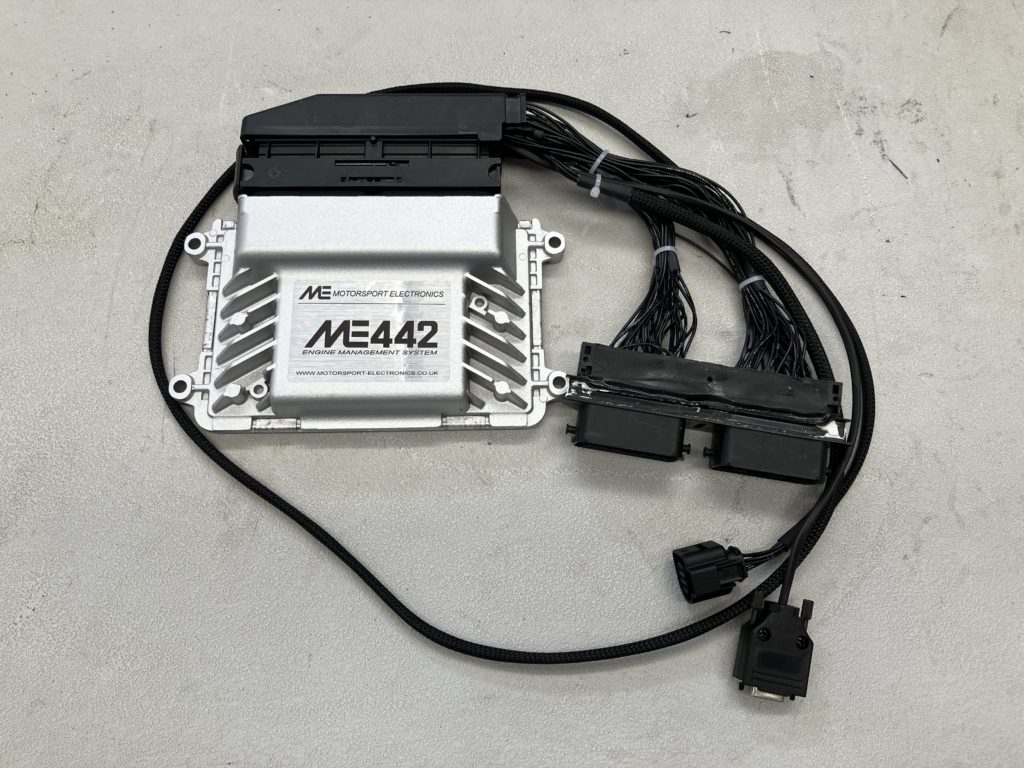
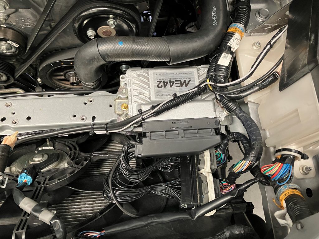
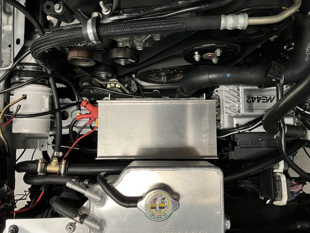
As part of the turbo install the factory ECU is being replaced with a Motorsport Electronics ME442. At 10psi the factory mass air flow sensor was close to being maxed out even though it is already mount in 3″ tube. Using the ME442 allows for VE Based fueling using manifold air pressure only. It also allows for boost control to be brought inside the ECU using RPM and throttle position. This will be important when reintroducing the electric supercharger.
Motorsport Electronics ME442ME442 installed
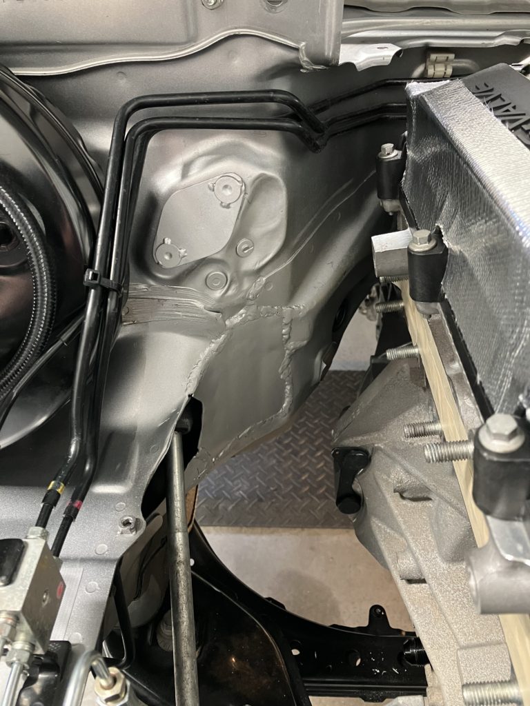
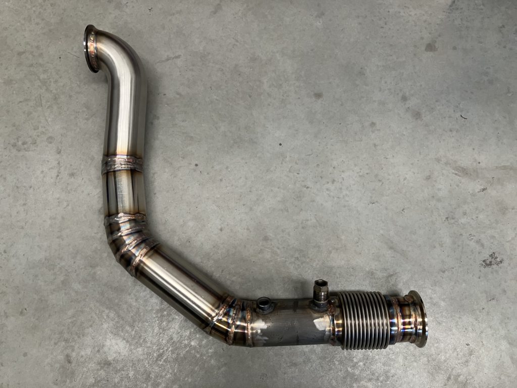
Next step was fabricating the dump. As well as relocating the clutch slave cylinder, the firewall was massaged slightly to give extra clearance. Coming out of the back of the turbo a tight radius mandrel 90-degree bend was used with the remainder made of straight and pie cut 3″ 304 stainless steel tube.
Massaged firewallDump pipe
So naturally the intercooler will be relocated to the front of the car. It sits directly in front of the engine to keep intercooler pipework as short as possible and removal of the MAF sensor has helped this cause. Removal of the MAF means we have to install an intake air temperature sensor downstream of the intercooler.
Intercooler mount
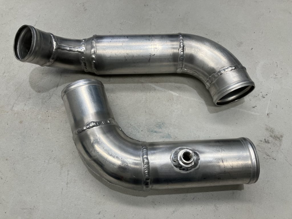
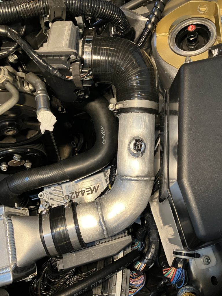
The outlet of turbo is 2″. We immediately expand out to 2.5″ and maintain this diameter through the intercooler and all the way to the throttle body.
Intercooler pipeworkIntercooler hot side pipeIntercooler cold side pipe
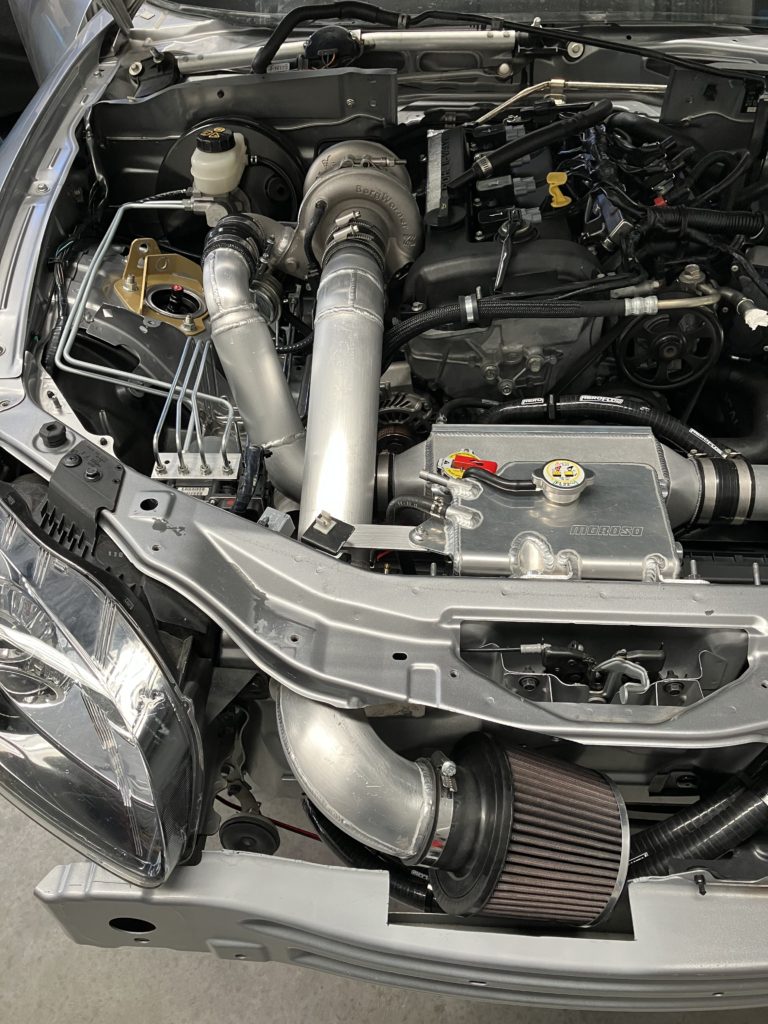
Turbo inlet pipework was fabricated to draw cold air from behind the front bumper but in front of radiator.
Turbo inlet pipework and air filter
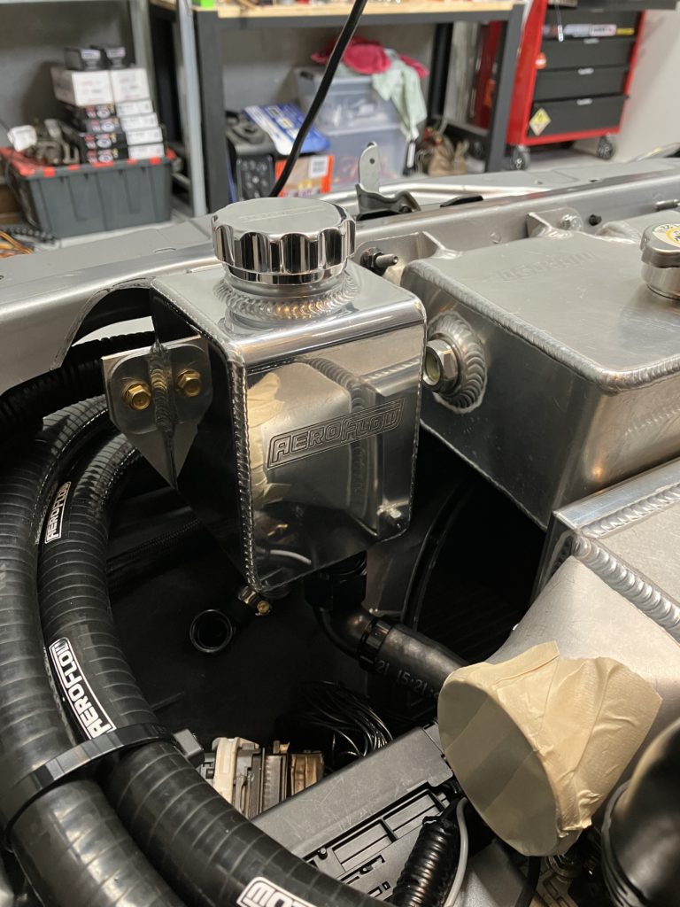
The intercooler and pipework required the removal of the battery and power steering reservoir from their OEM locations. An aluminium power steering reservoir has been mounted next to the coolant expansion tank. The battery has been moved to the boot.
Power steering reservoirBattery in boot
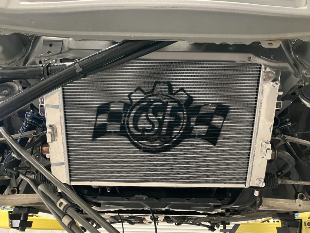
There is no way the tiny OEM radiator is going to keep up with the cooling demands on the new turbo setup. Besides the extra cooling demand form the extra power that will be produced, we are also using engine coolant to cool the oil and now the turbo as well. A CSF high performance radiator has been installed. This unit is considerable thicker than stock and is all aluminium design so don’t have to worry about plastic end tanks failing.
CSF aluminium radiator
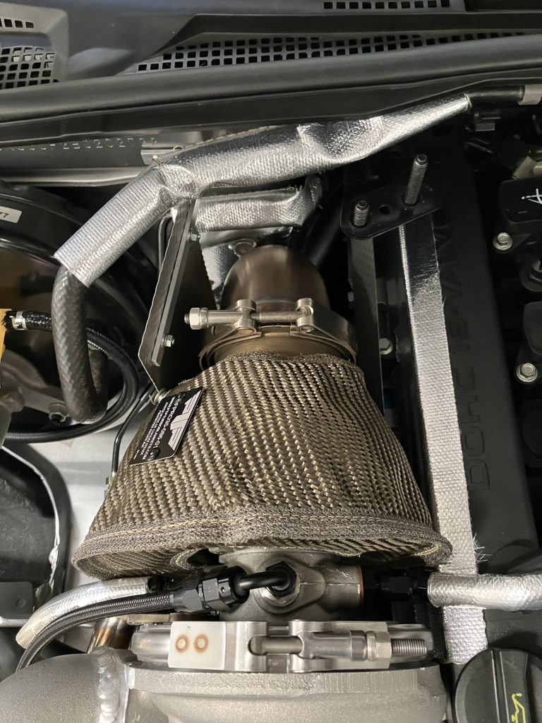
To manage under bonnet temperatures and protect temperature sensitive components heat shielding was installed around the turbo and dump. For the turbo a PTP blanket was used to cover the turbine housing. Heat reflective tape was used on the firewall and rocker cover, heat reflective sleaving was used to protect hoses and brake lines, and some heat shields were fabricated.
Heat shieldingHeat shielding
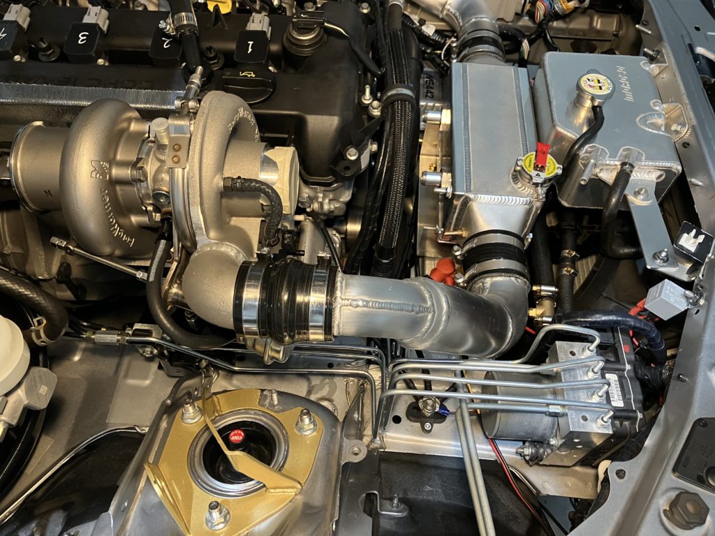
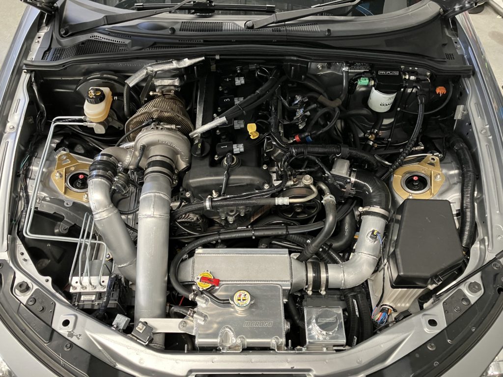
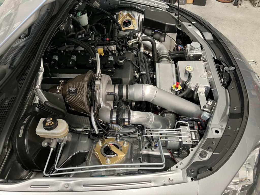
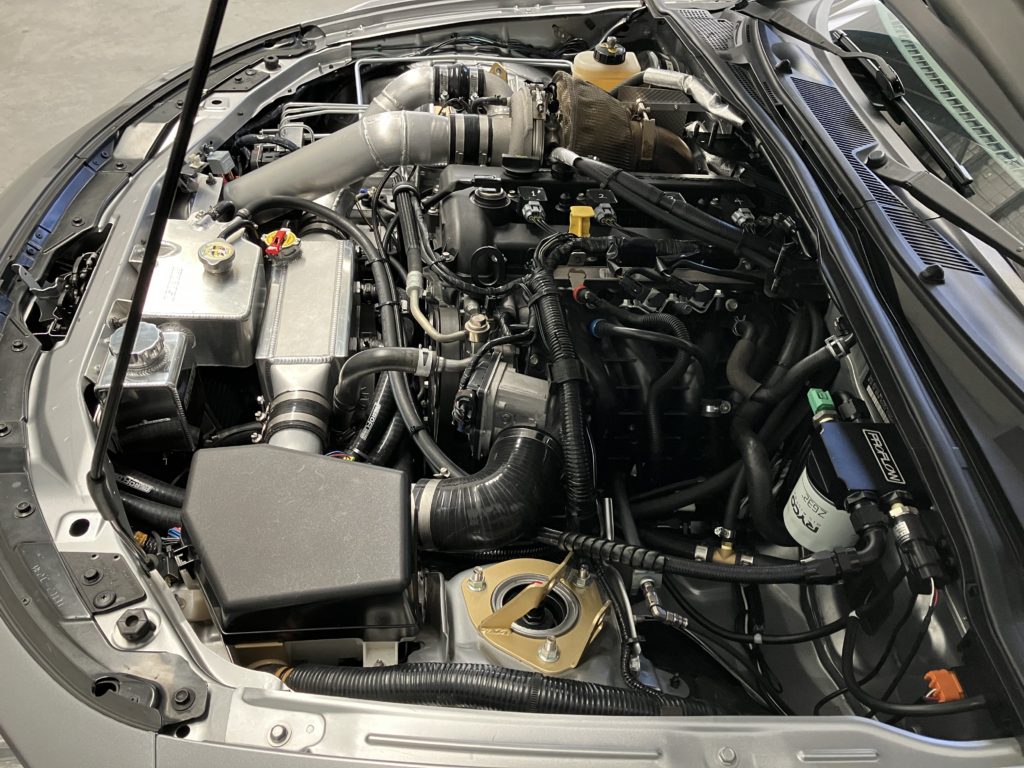
Turbo install complete and ready for testing and tuning.