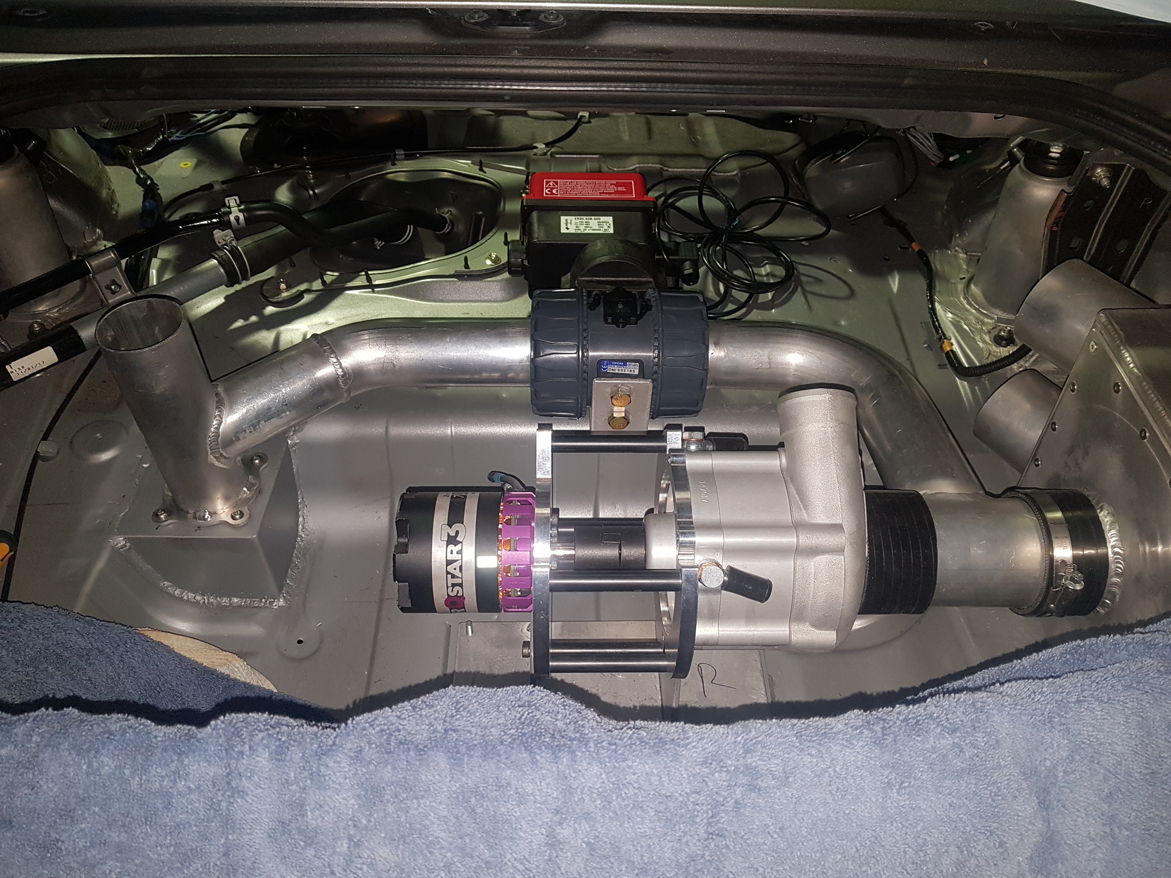
The bypass valve will be open when the system is off (bypassing the compressor and intercooler) and close when the e-charger is running. Original I was going to use electronic throttle body as the bypass valve but changed to a DN50 ball valve to ensure tight shutoff and no boost leaks when the system is in operation. A electric actuator was selected for the valve so that starting and stopping the system could be automated.
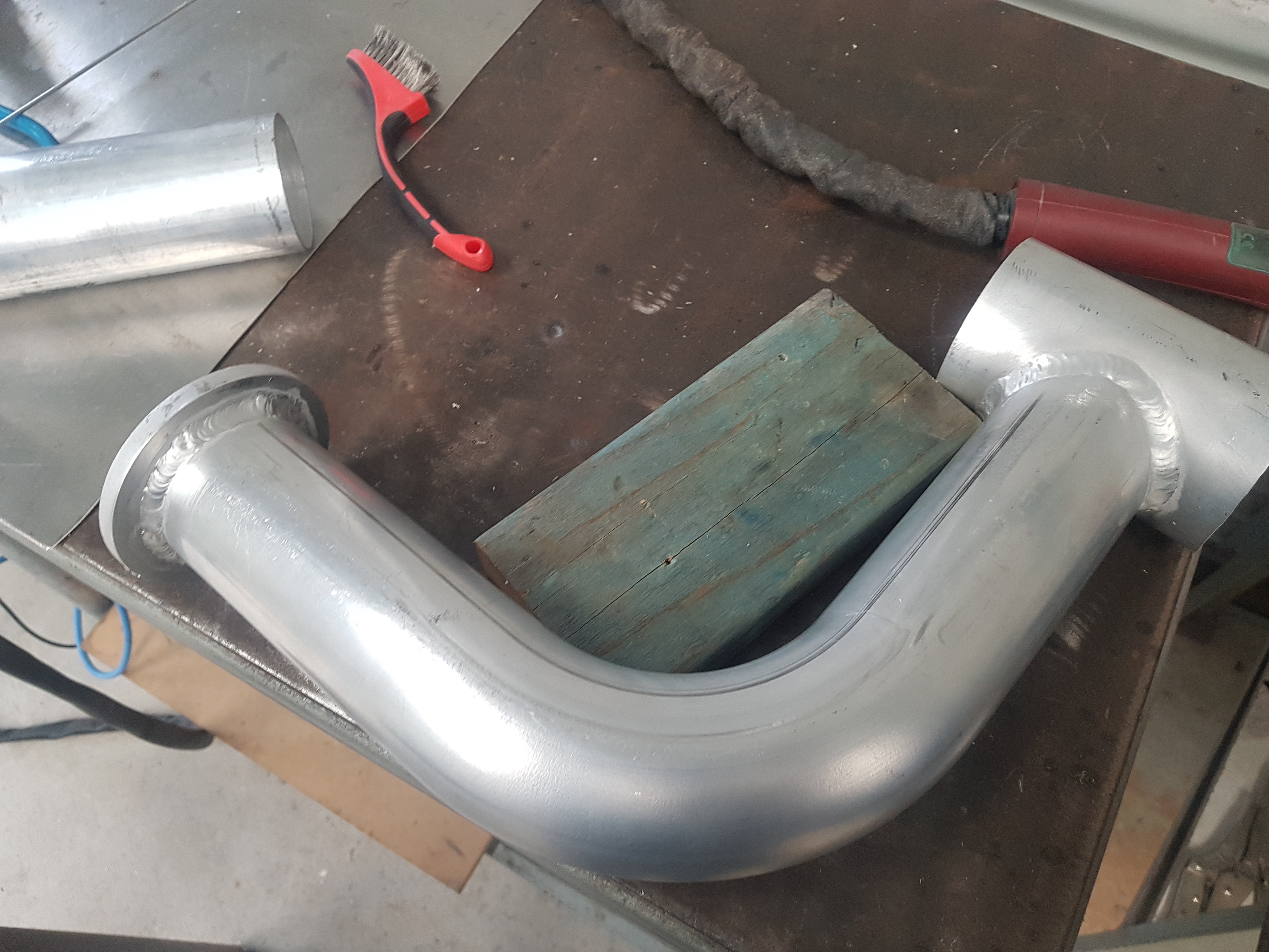
The bypass valve will be plumbed in using 2.5 inch aluminium tube. The upstream side of the bypass valve will tee-in between the airbox outlet and compressor inlet.
Trial fit of bypass valve upstream tubingCompleted bypass valve upstream tubing
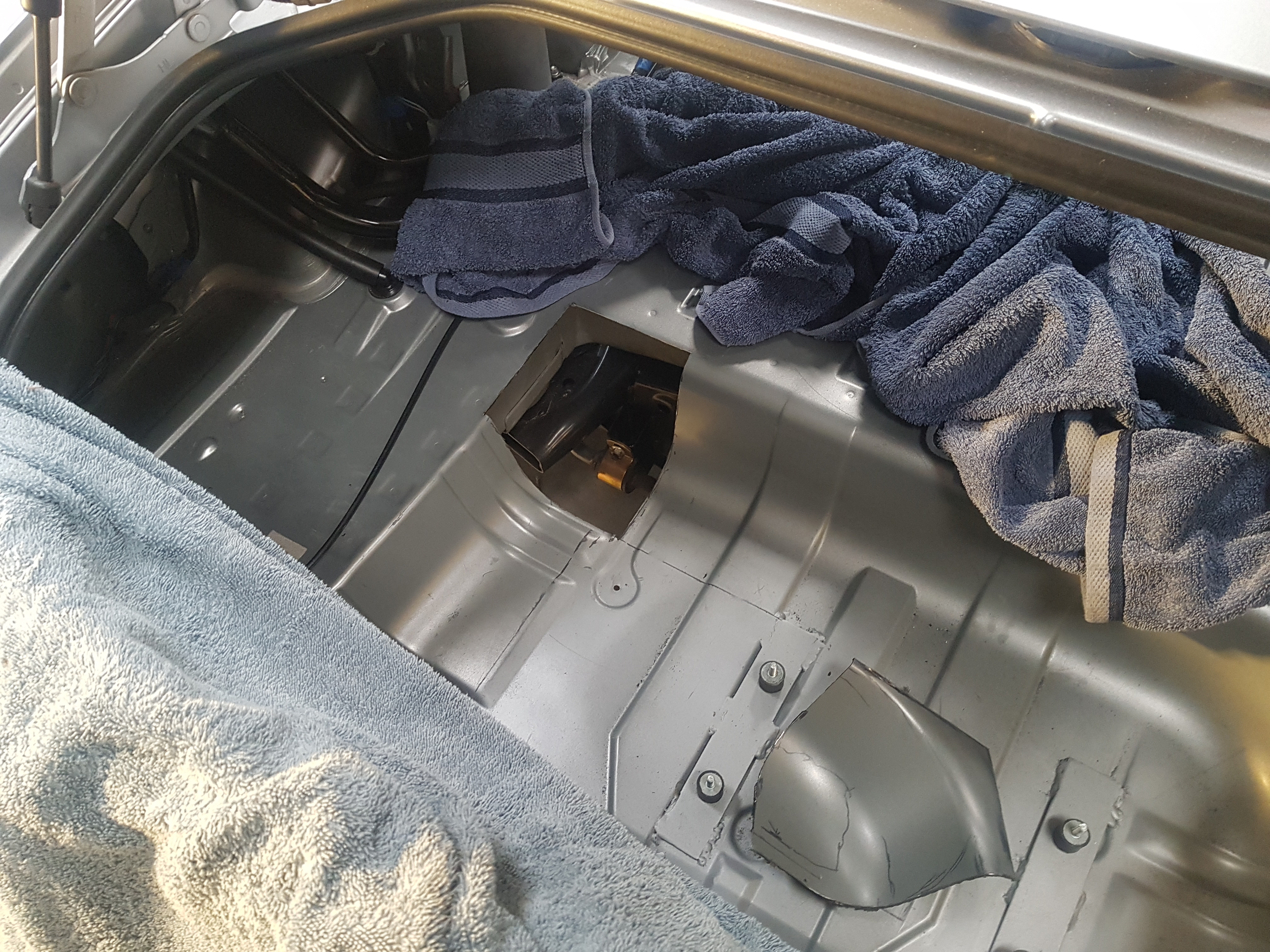
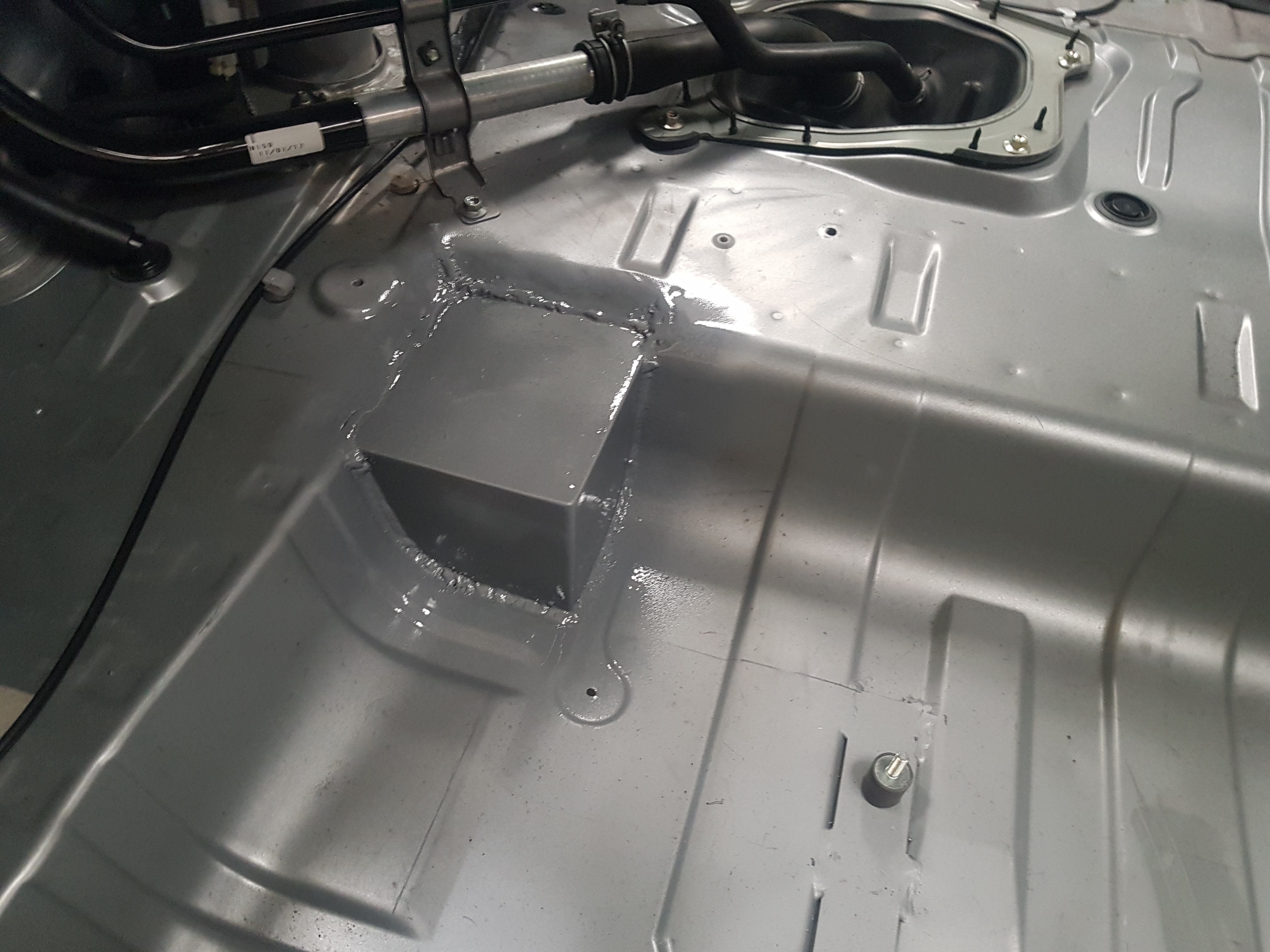
The bypass valve downstream tube-work tees in downstream of the intercooler. This is the location at which the charge pipe will penetrate the floor of the vehicle before heading towards the engine. To allow this a whole was cut in the floor and a box fabricated to receive a flange welded to the charge pipe.
Whole for charge pipe penetrationBox fabricated to receive charge pipe and flangeCompleted bypass valve installation
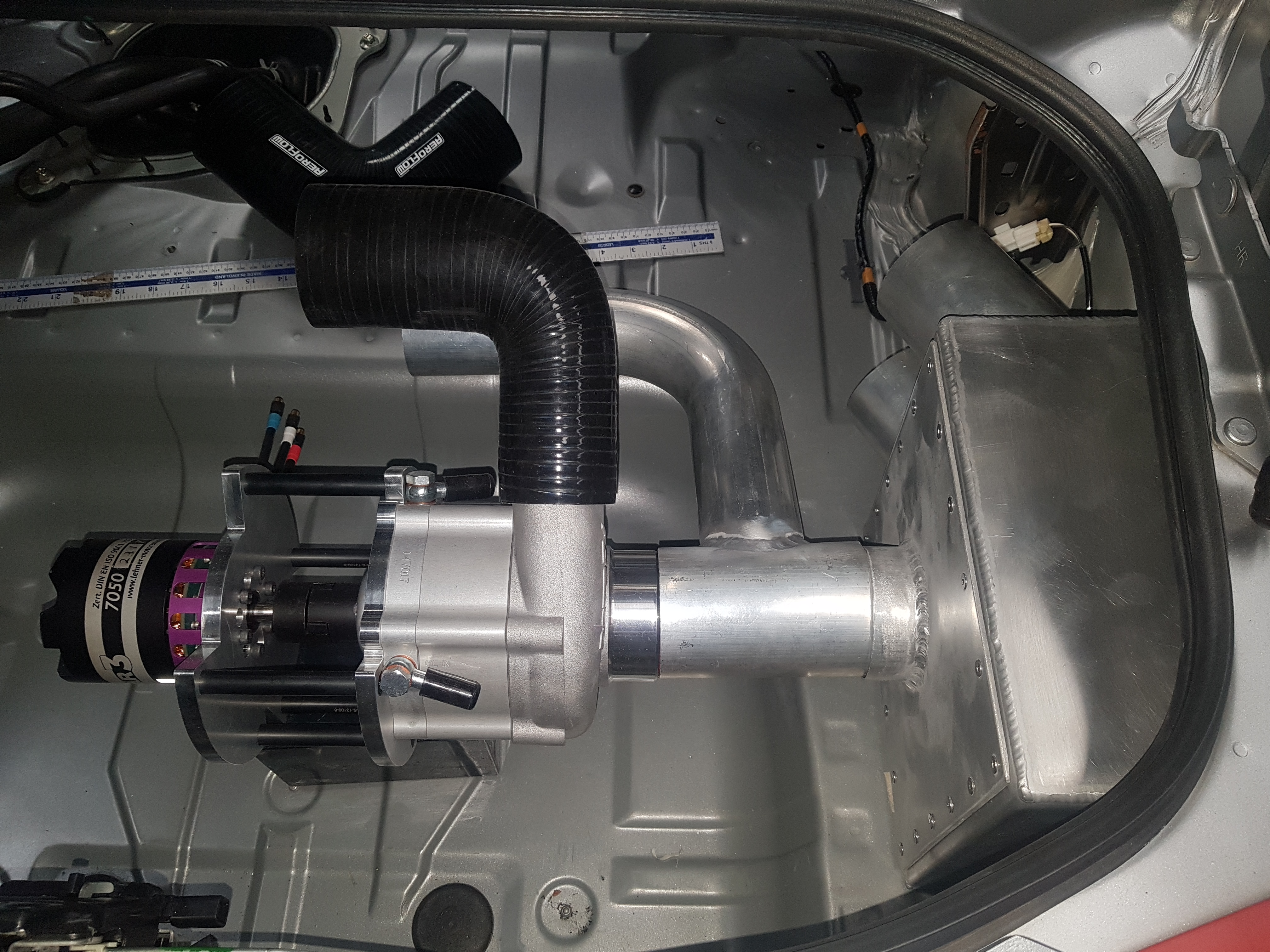
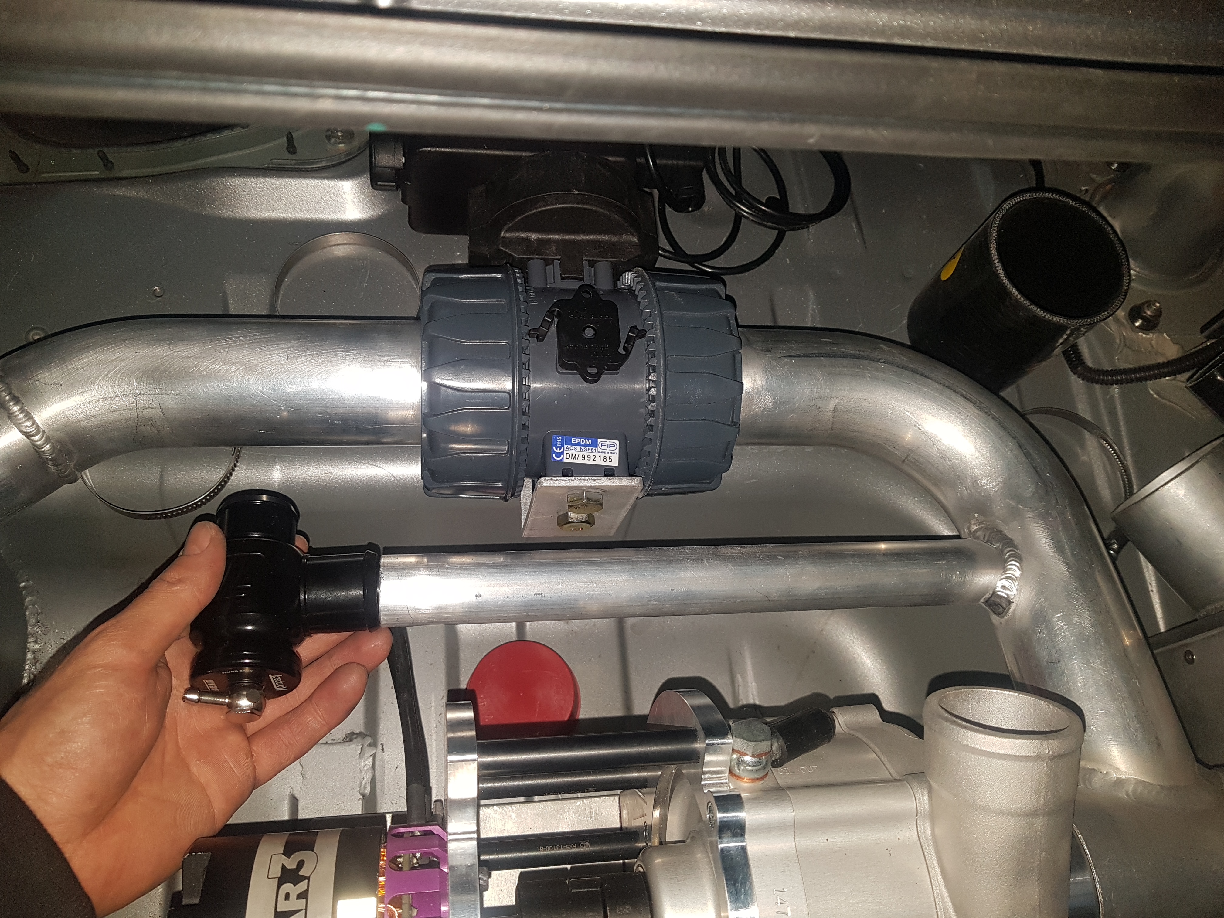
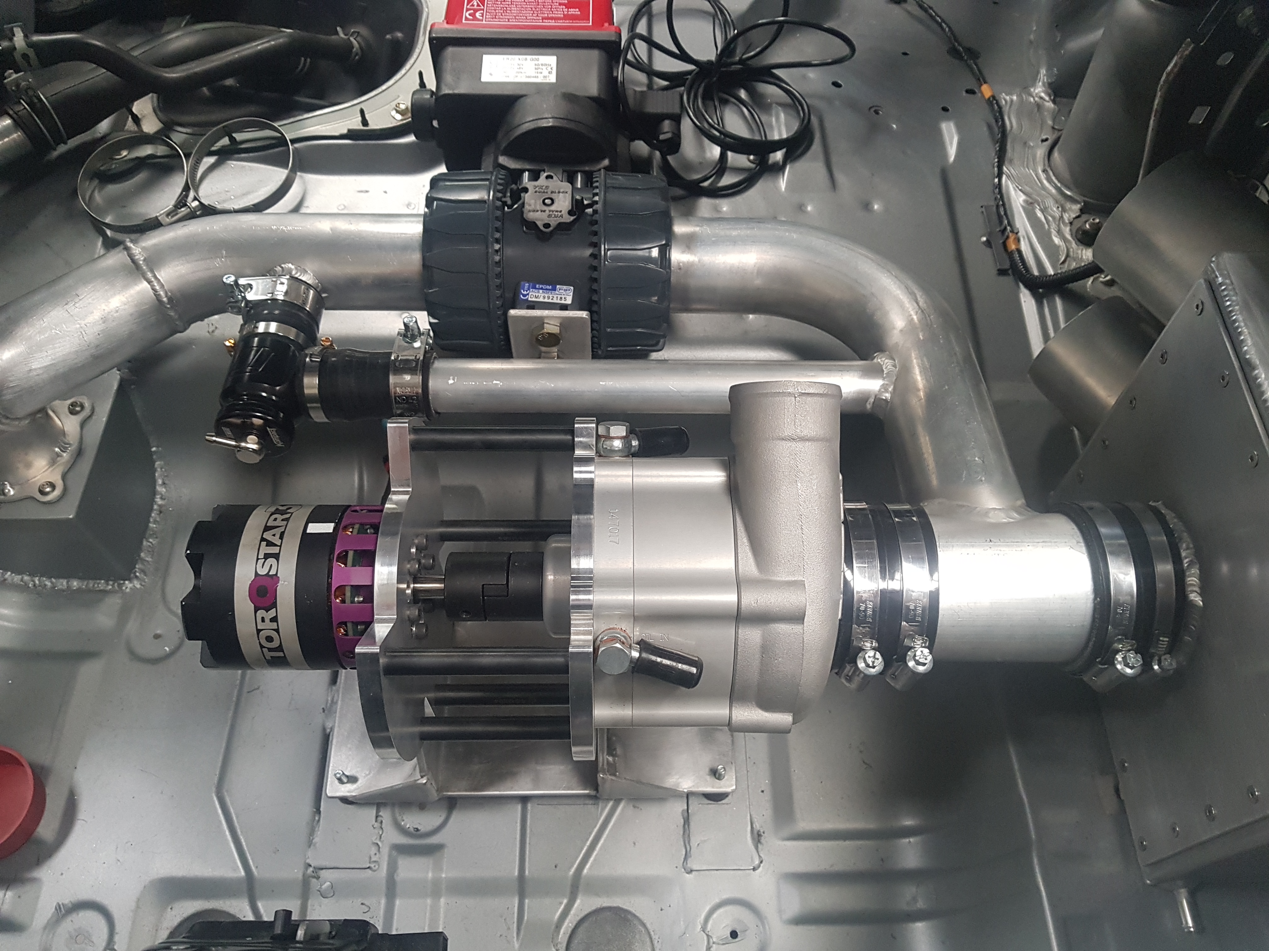
The recirculation valve also bypasses the compressor however its purpose is to prevent compressor surge when the system is in operation. The Turbosmart Kompact plumb back valve was selected. Initially this valves operation will be purely pneumatic using intake manifold vacuum to operate, however this may change after testing.
The recirculation valve was plumbed in using 1.25 inch aluminium tube.
Recirculation valve installed around bypass valveCompleted recirculation valve installation
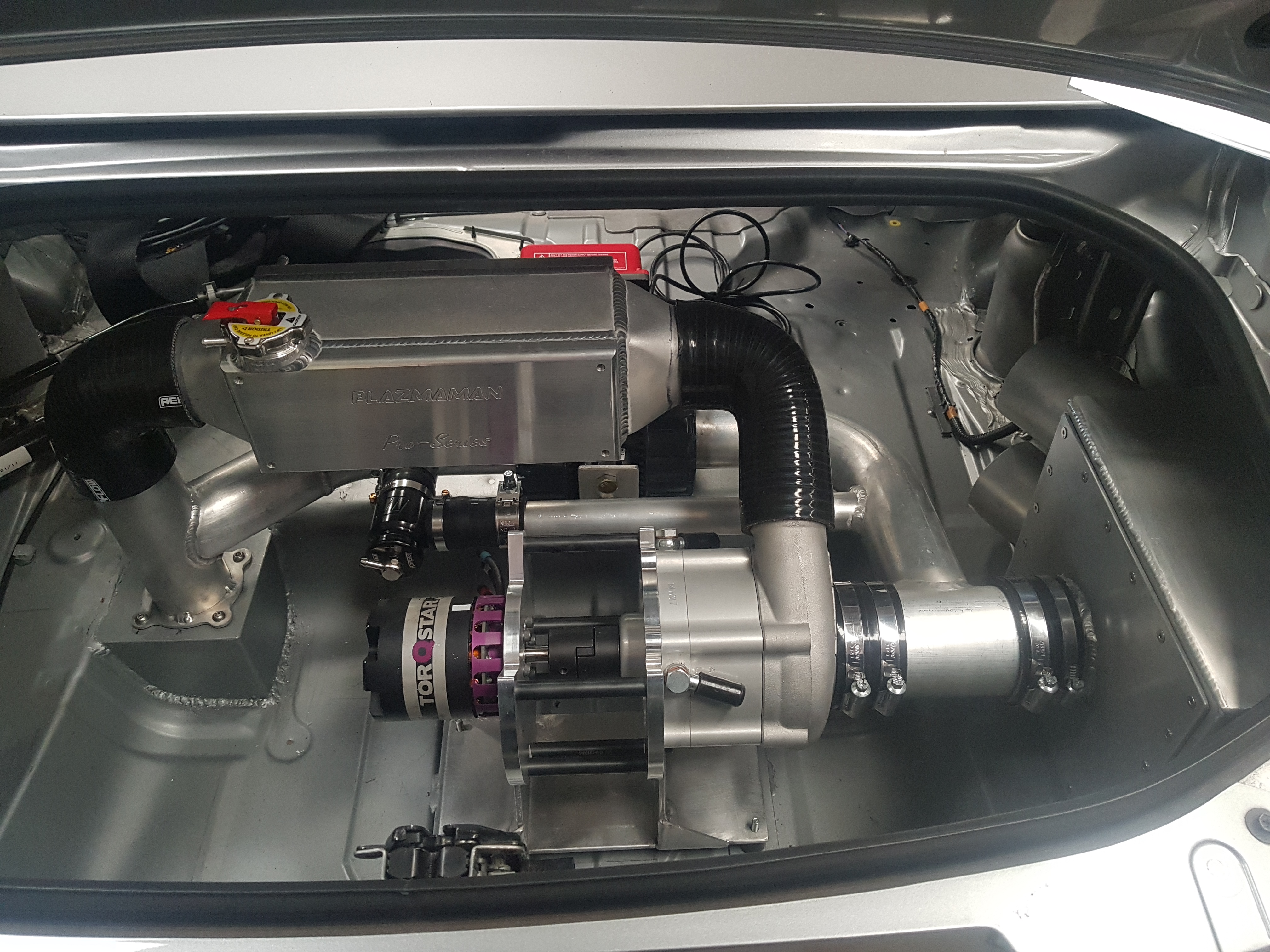
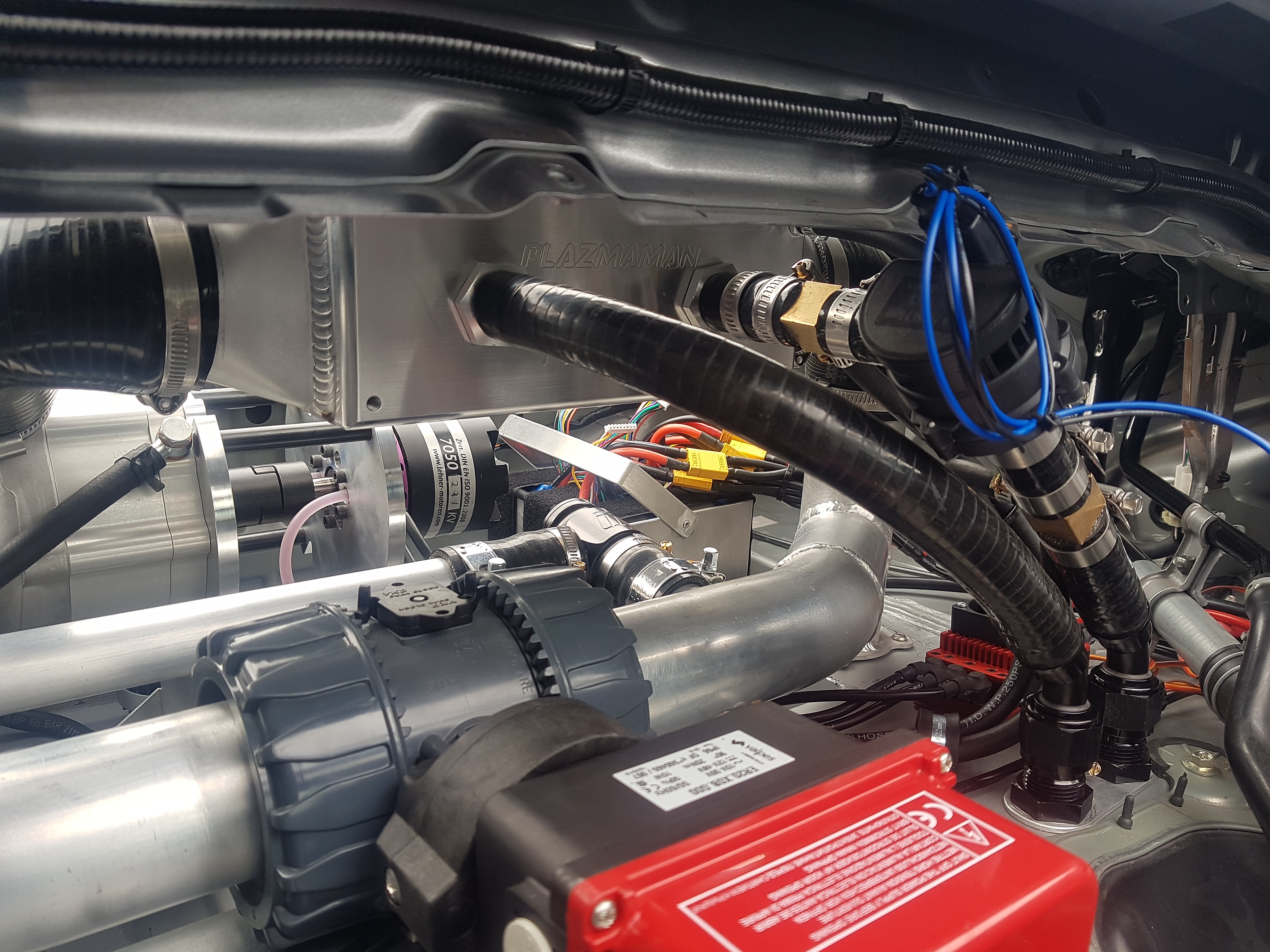
The intercooler is a water to air heat exchanger manufactured by Plazmaman. Silicon elbows were used for connecting intercooler to compressor and charge pipe due to space constraints.
Intercooler installation
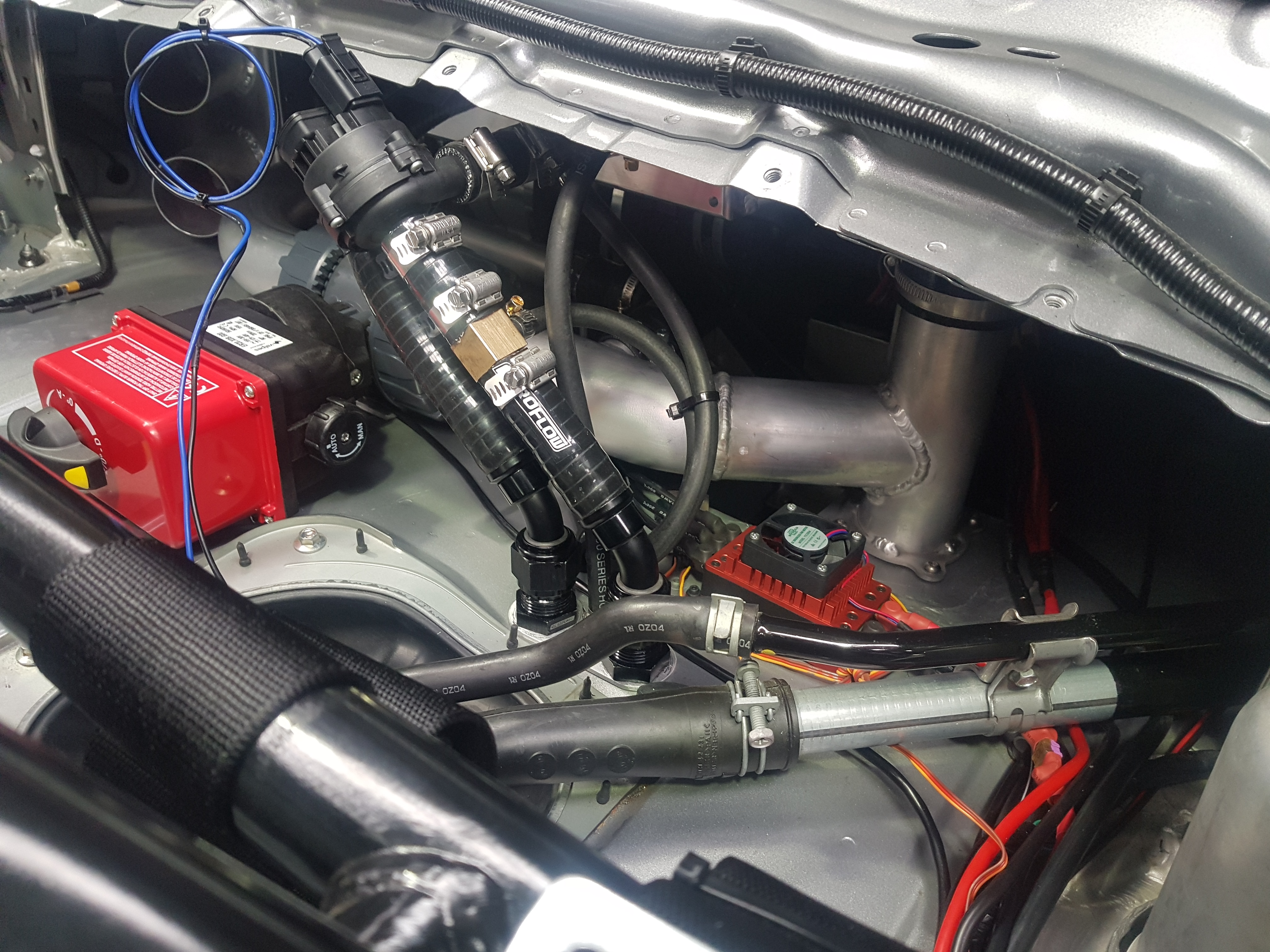
The radiator for the intercooler water circuit will be mounted in the front of the factory radiator. Water lines pass through the floor just behind the fuel tank then follow the transmission tunnel towards the front of the vehicle.
Water line connections to intercooler
A Bosch water pump is used for circulate water through the system. A tee was installed on the suction and discharge of the pump. These off takes reduce to smaller hose before connecting to electric motor for cooling.
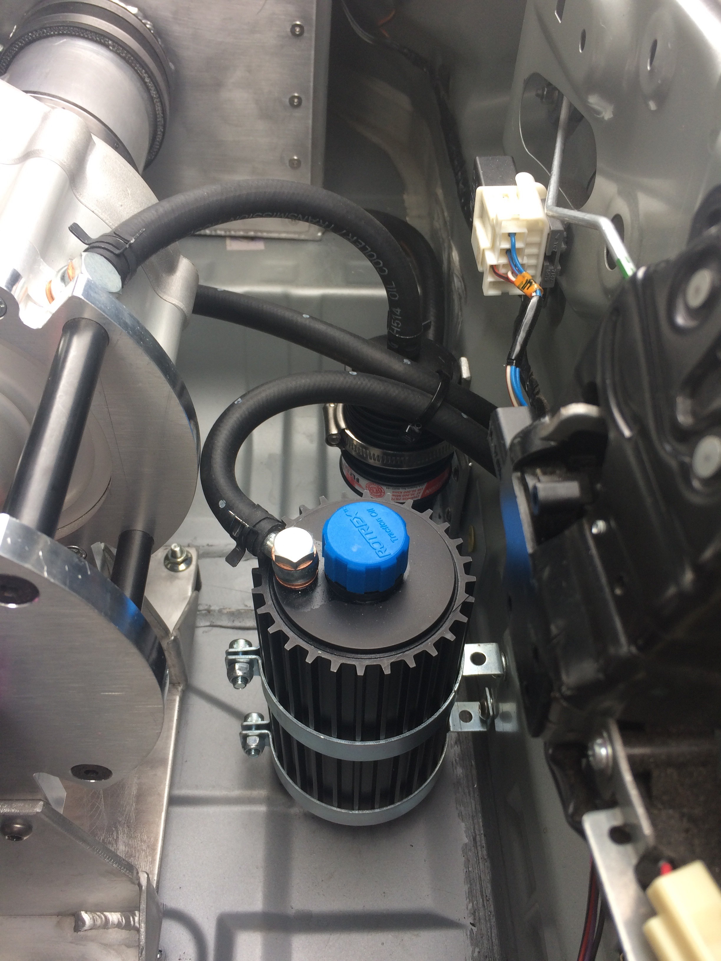
The oil circuit for the Rotrex compressor is self contained with a integrated oil pump. The oil reservoir and oil filter were installed close to the compressor.
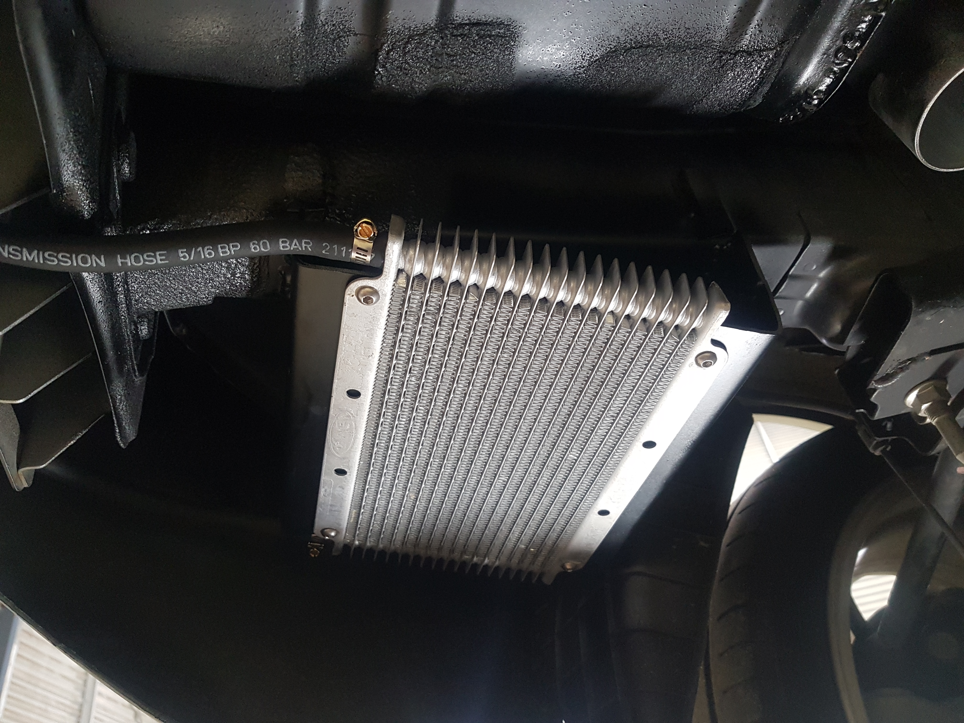
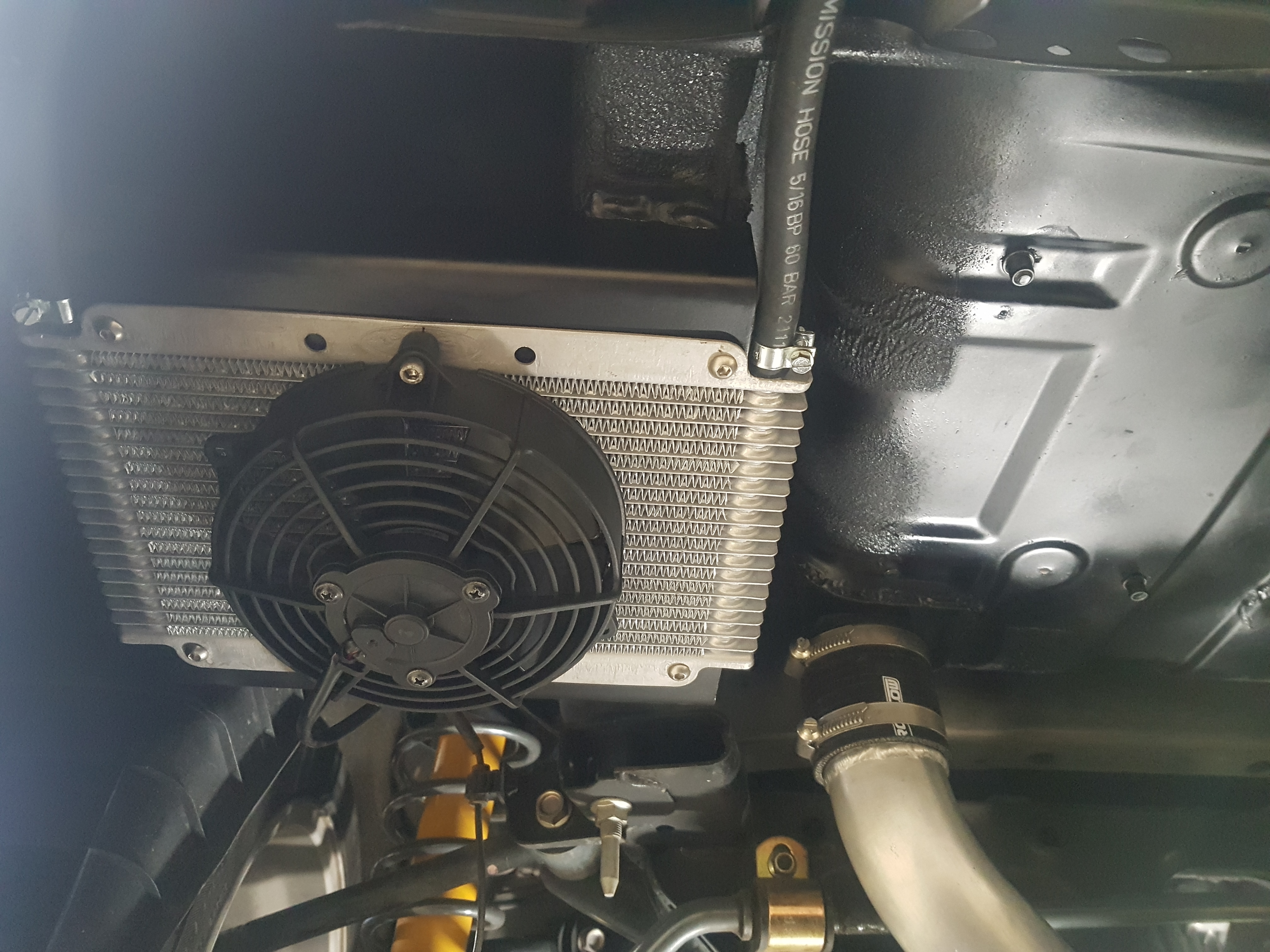
A PWR oil cooler was sourced for cooling as recommended by Rotrex. It was decided to mount the cooler under the floor behind the left rear wheel to keep the oil lines as short as possible. A electric fan was added to the cooler to ensure sufficient air flow.
This is where things get a bit tricky. The plan was to run 2.5 inch aluminium tube from the compressor in the rear all the way to the engine bay. Just before the throttle body the diameter will increase to 3 inch and the factory mass air flow (MAF) sensor would be mounted in this section.
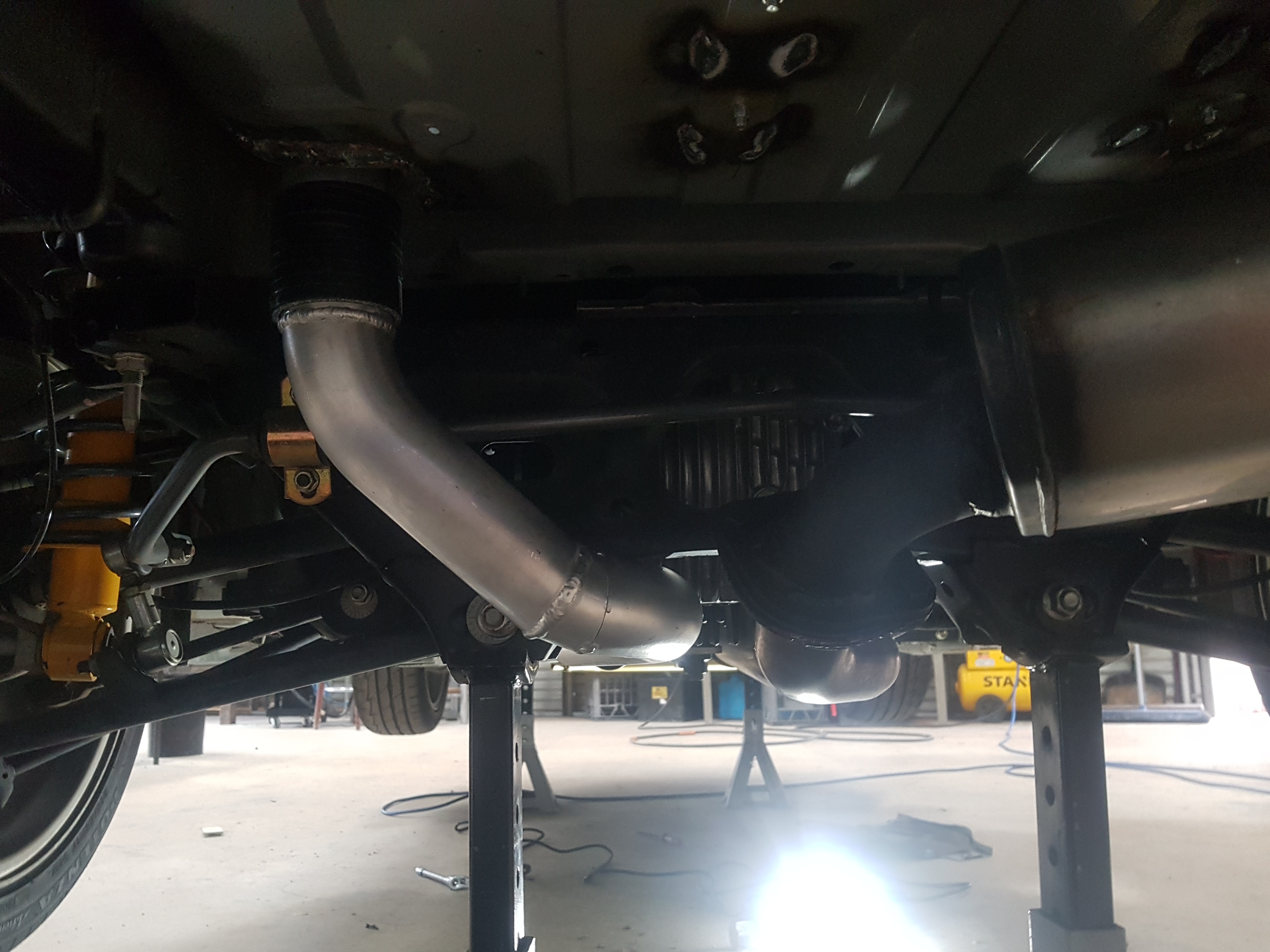
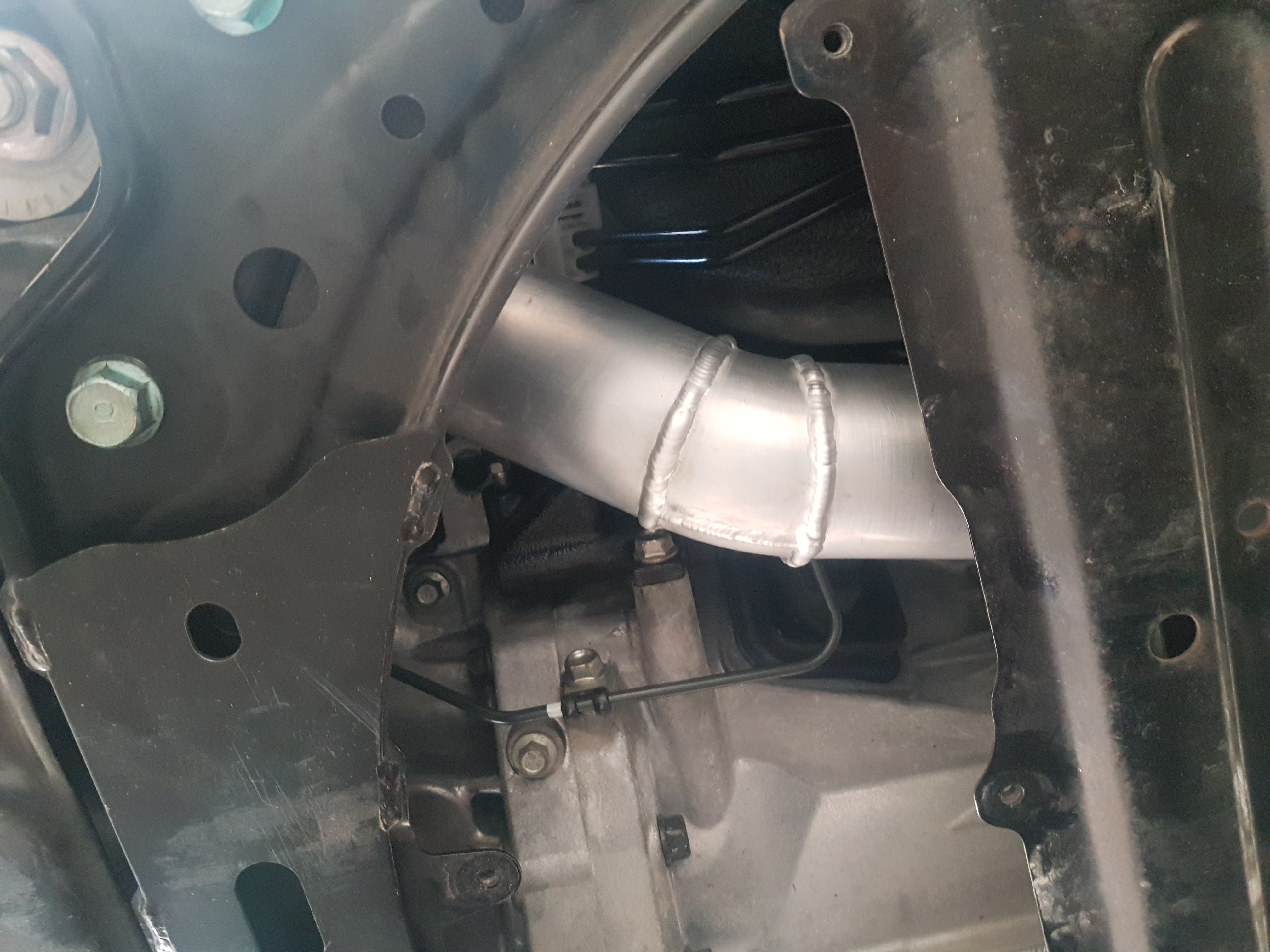
After passing through the floor in the boot the charge pipe goes under the diff.
Charge pipe path under diff
As the exhaust is on the right hand side of the gearbox and power plant frame (PPF), the charge pipe will need to be installed on the left hand side of the PPF. It became clear that clearance would be an issue.
View of transmission tunnel looking to front of vehicleSpace is a bit tight
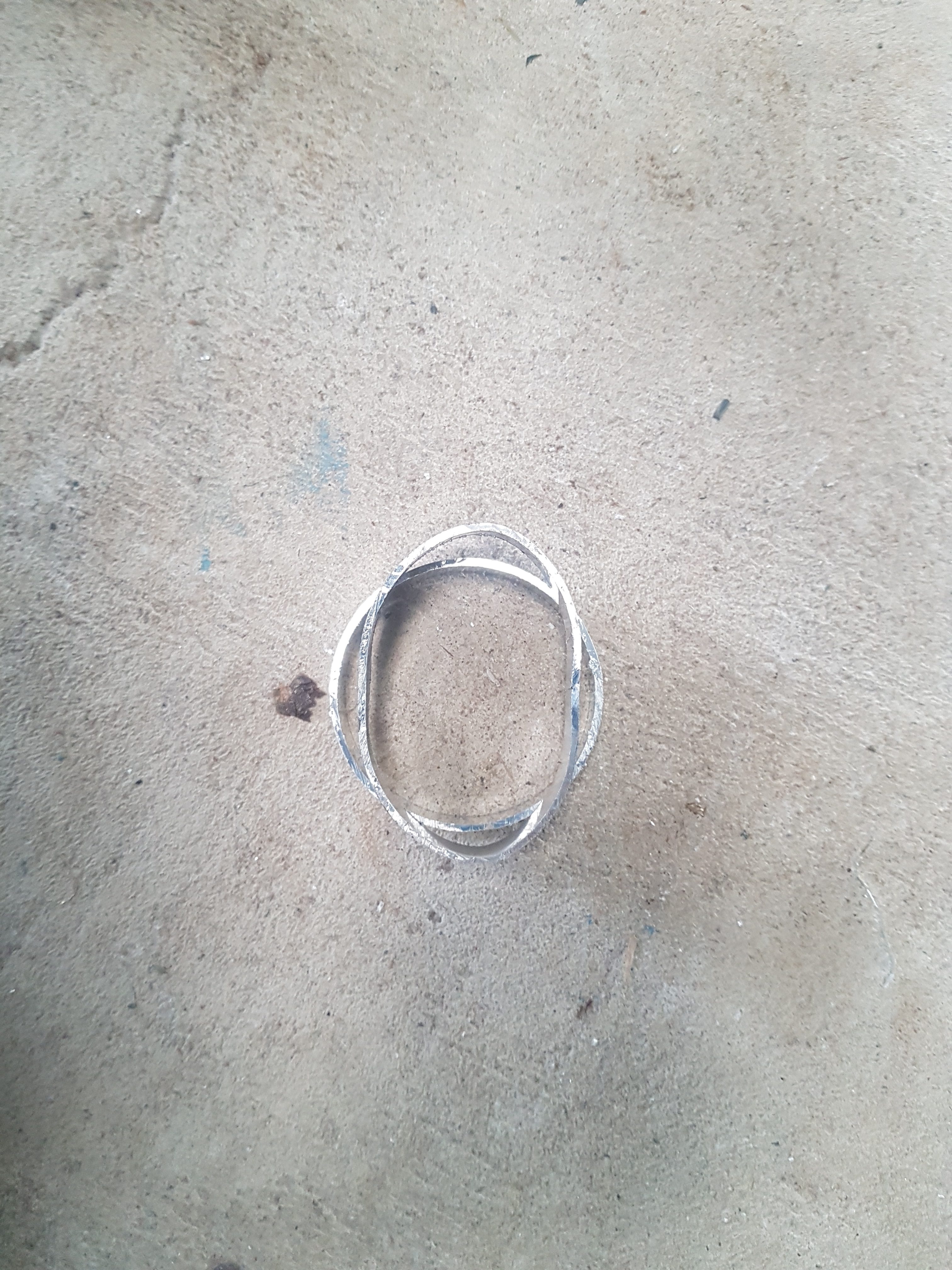
To get the tube through this space it would need to be crushed slightly to create an elliptical rather that circular cross section. This will not have a material effect on flow or pressure drop through this section. The transmission tunnel was also massaged to gain extra clearance.
Example of elliptical tube cross sectionInstalled charge pipeInstalled charge pipe
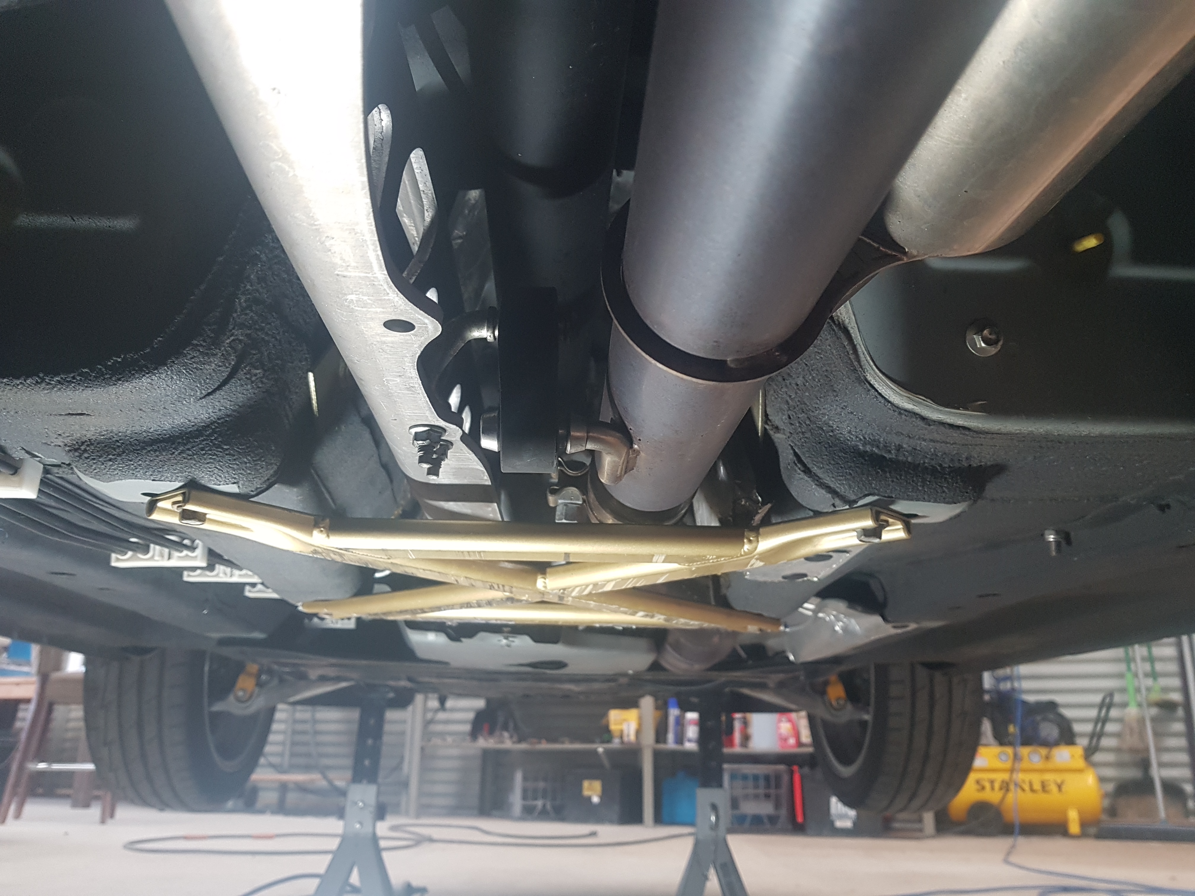
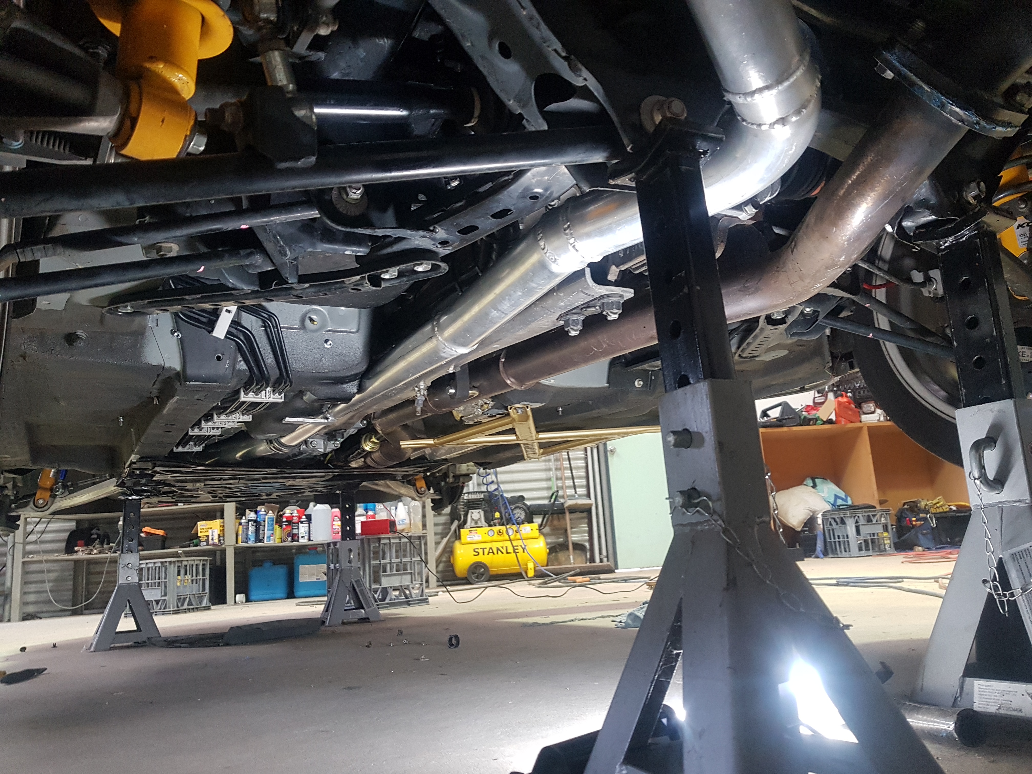
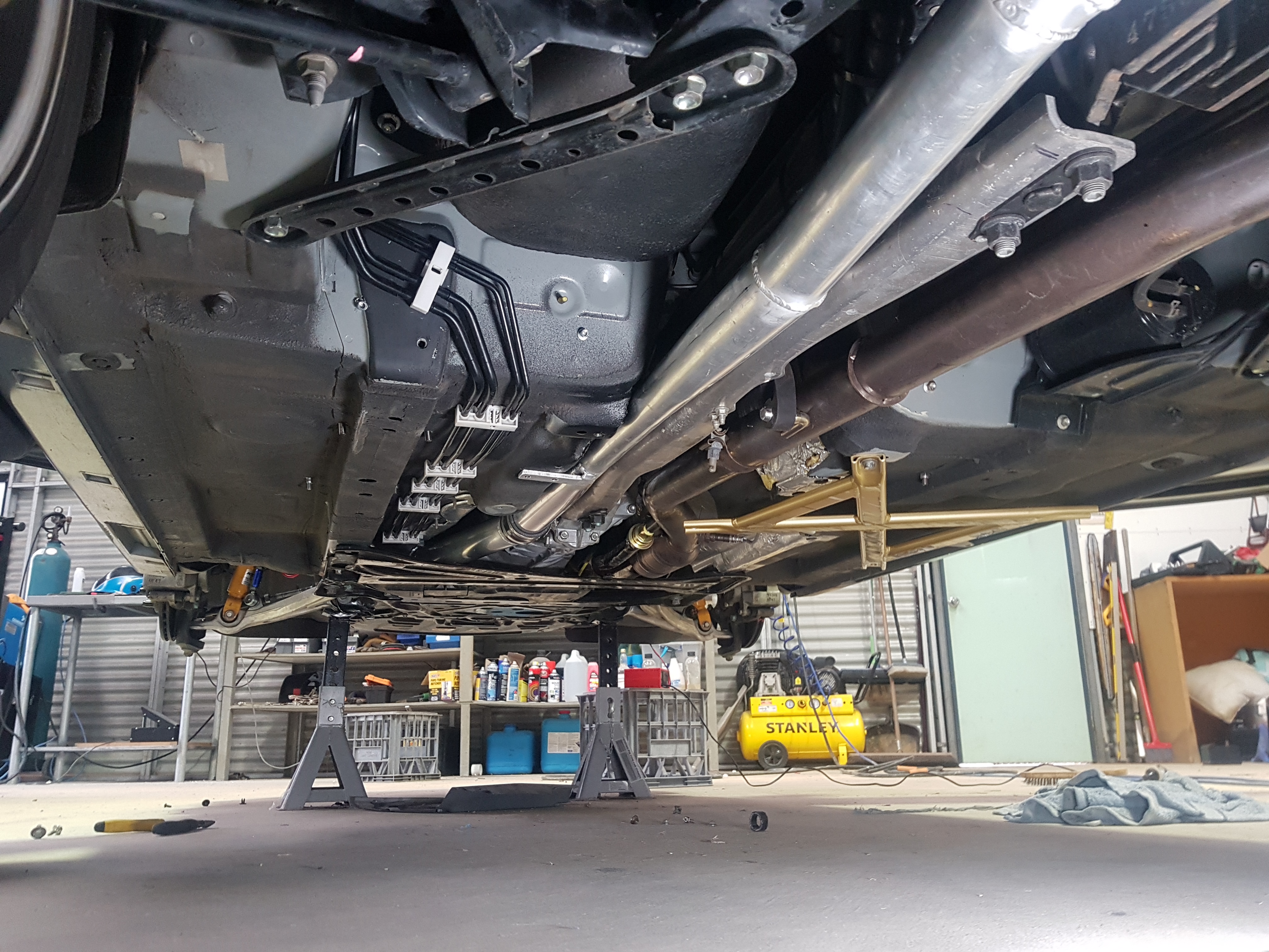
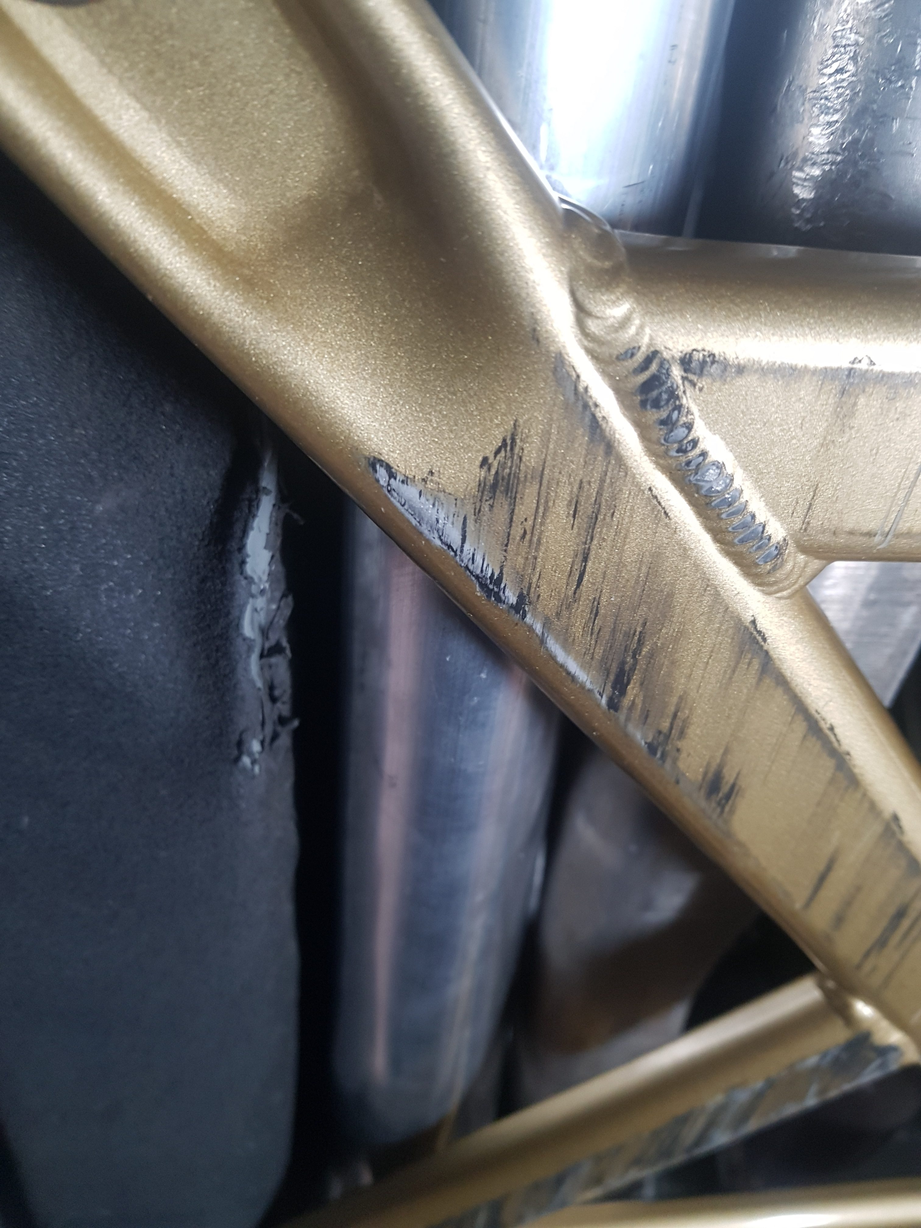
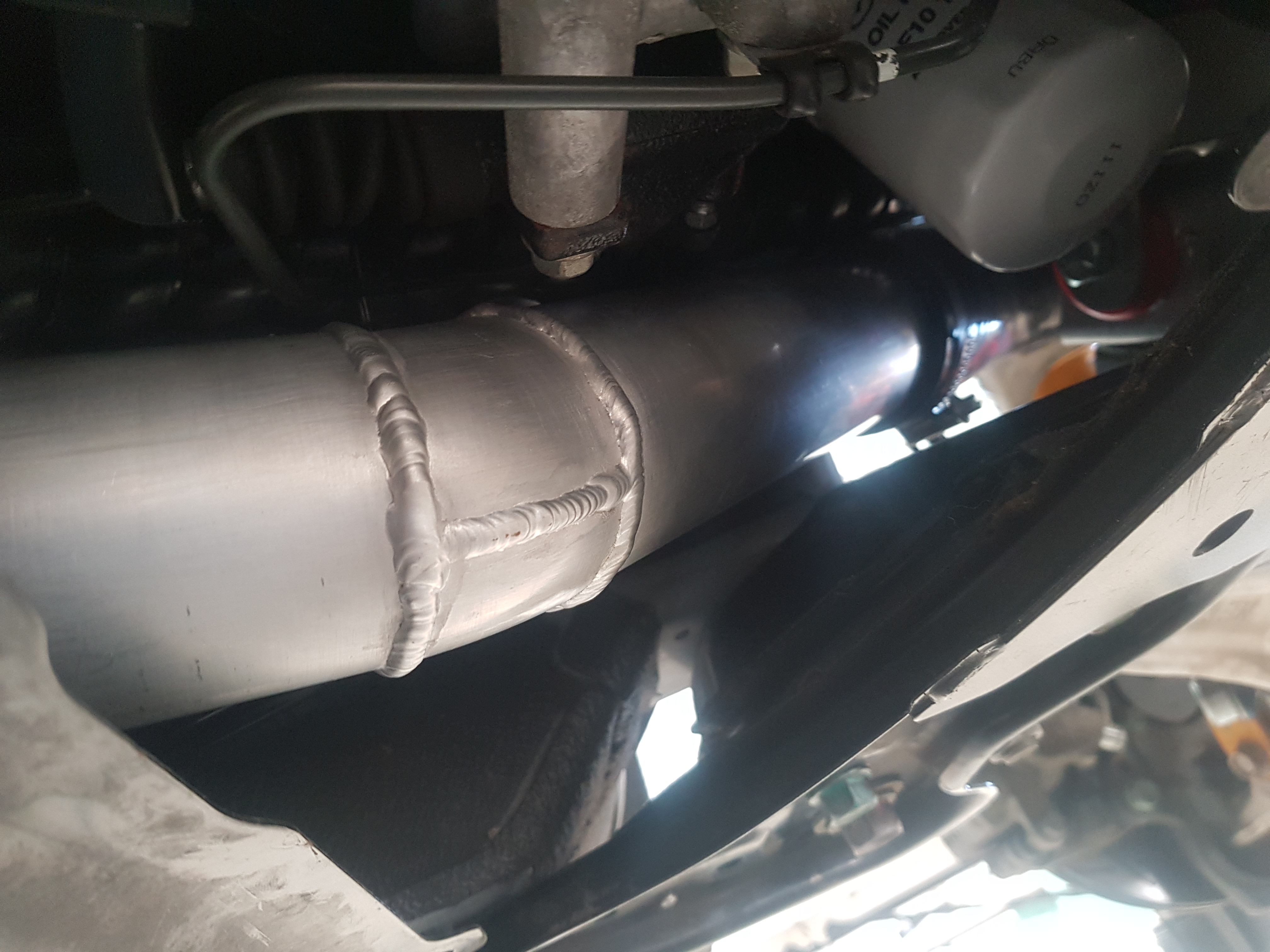
The tube fits above the under body cross brace so should be out of harms way. Although it doesn’t look it in the below pictures there is 10mm clearance either side of the charge pipe as it passes between the transmission tunnel and the PPF.
Charge pipe above cross brace
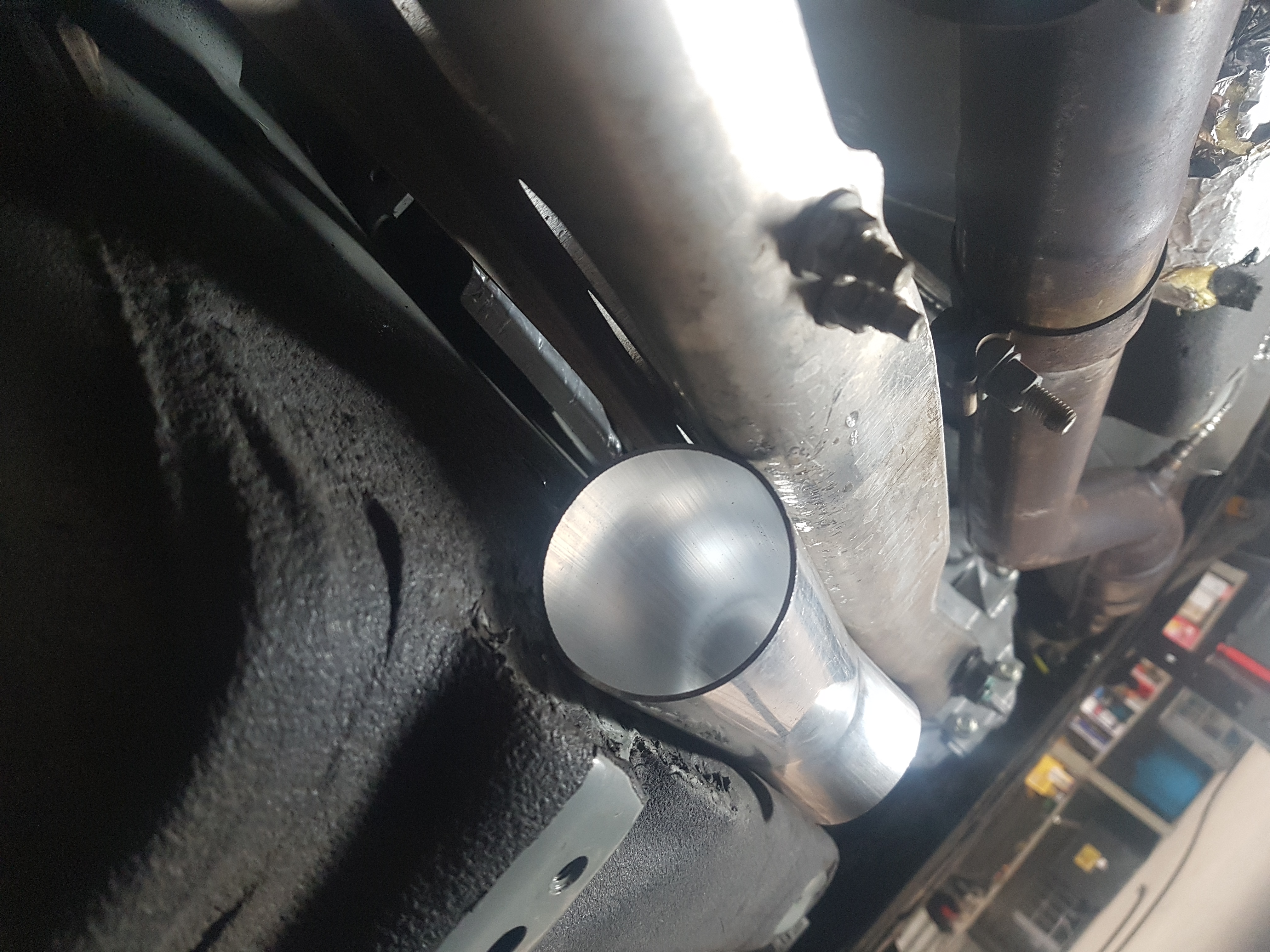
The next joint in the tube is at the gearbox output shaft after which the tube makes its way around the gearbox and bell housing.
Tube at gearbox bell housing
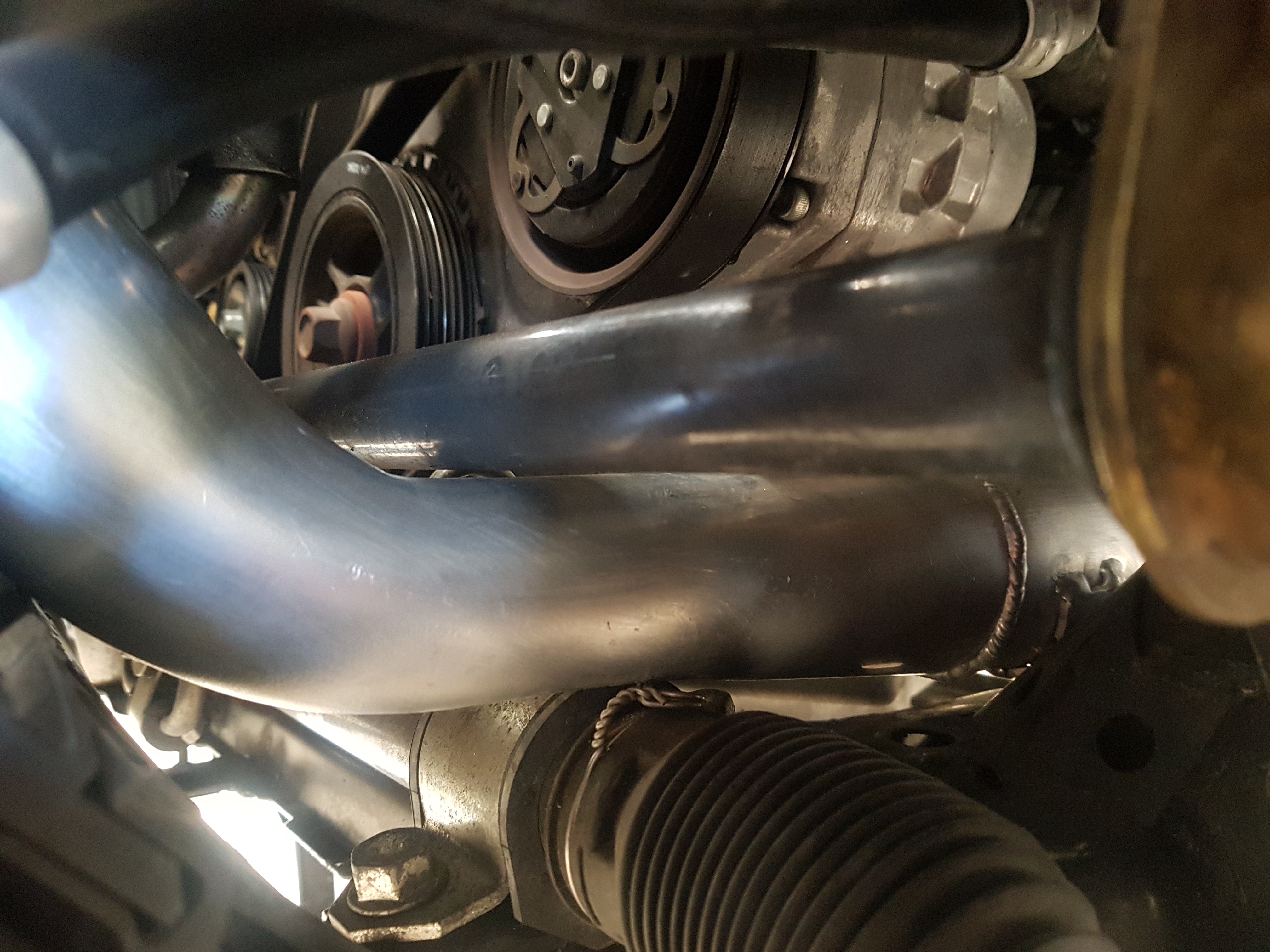
From the bell housing the tube runs along the left hand side of the motor around the left engine mount. At this time the factory engine mounts were replaced with polyurethane mounts. These mounts are physical smaller than the factory mounts allowing more room for the charge pipe. They will also better handle the increase in torque from the supercharged engine.
Charge pipe running past left hand side of engine. Oil filter remains serviceable
The next issue was squeezing between the front anti-roll bar and steering rack. The tube needed to be crushed slightly again. Clearance is tight but sufficient.
Tube passing between anti-roll bar and steering rack
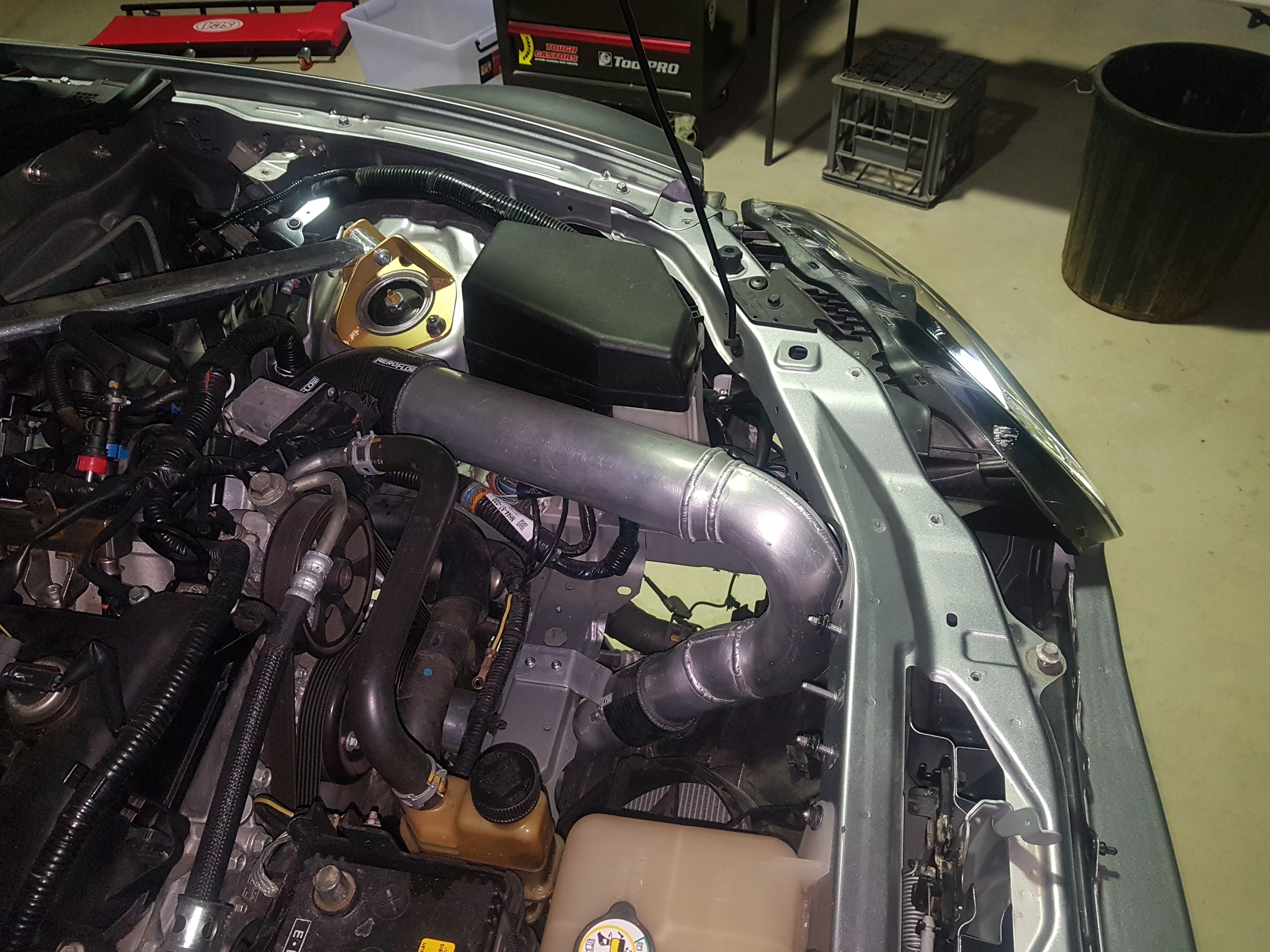
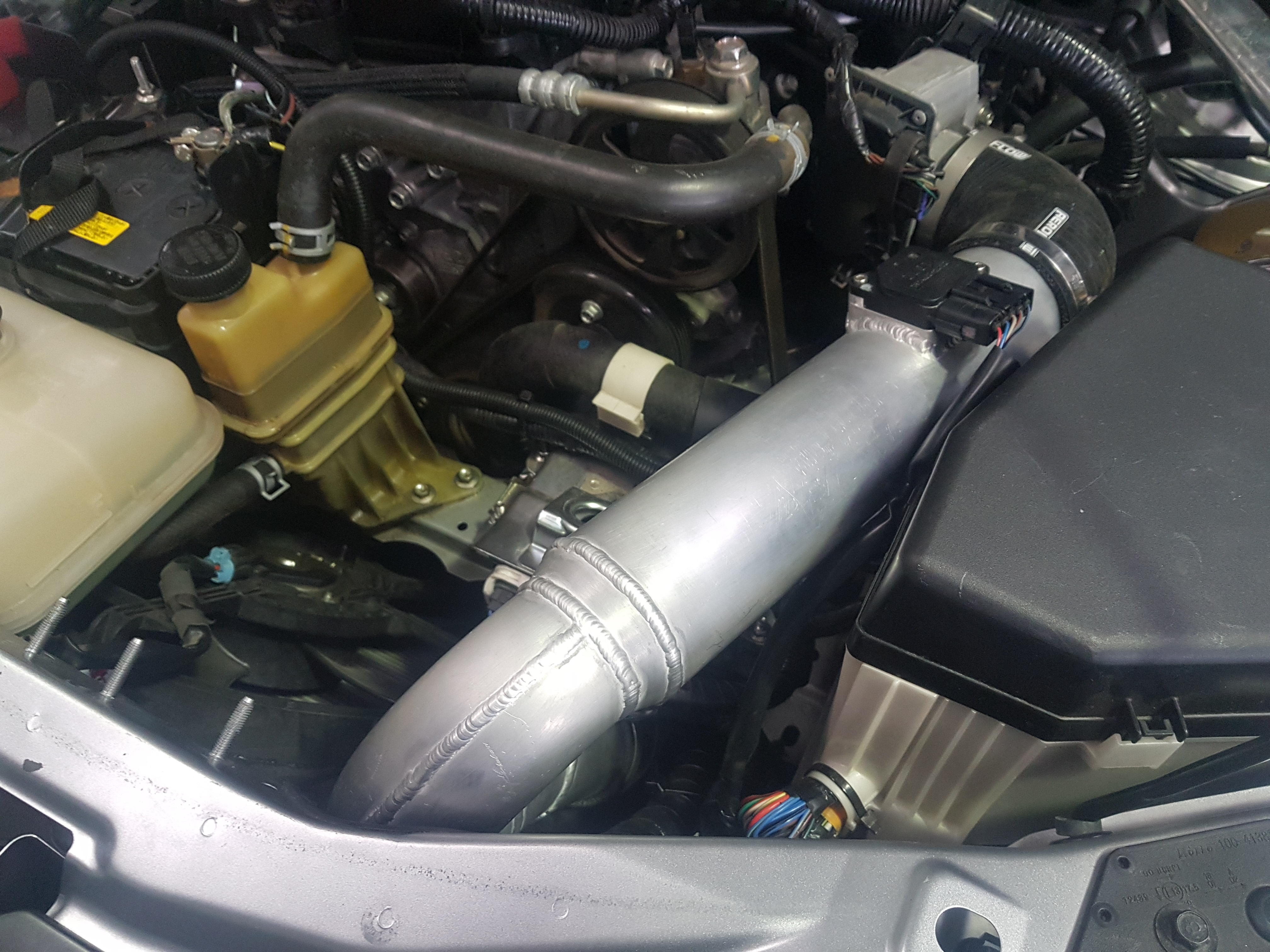
The final step was to bring the pipe up and rotate 180 degrees to connect to engine throttle body. After the rotation the tube size was increased form 2.5 inch to 3.0 inch. A Denso MAF flange was welded onto the 3.0 inch section and final connection to throttle body is made using a silicon 90 degree elbow.
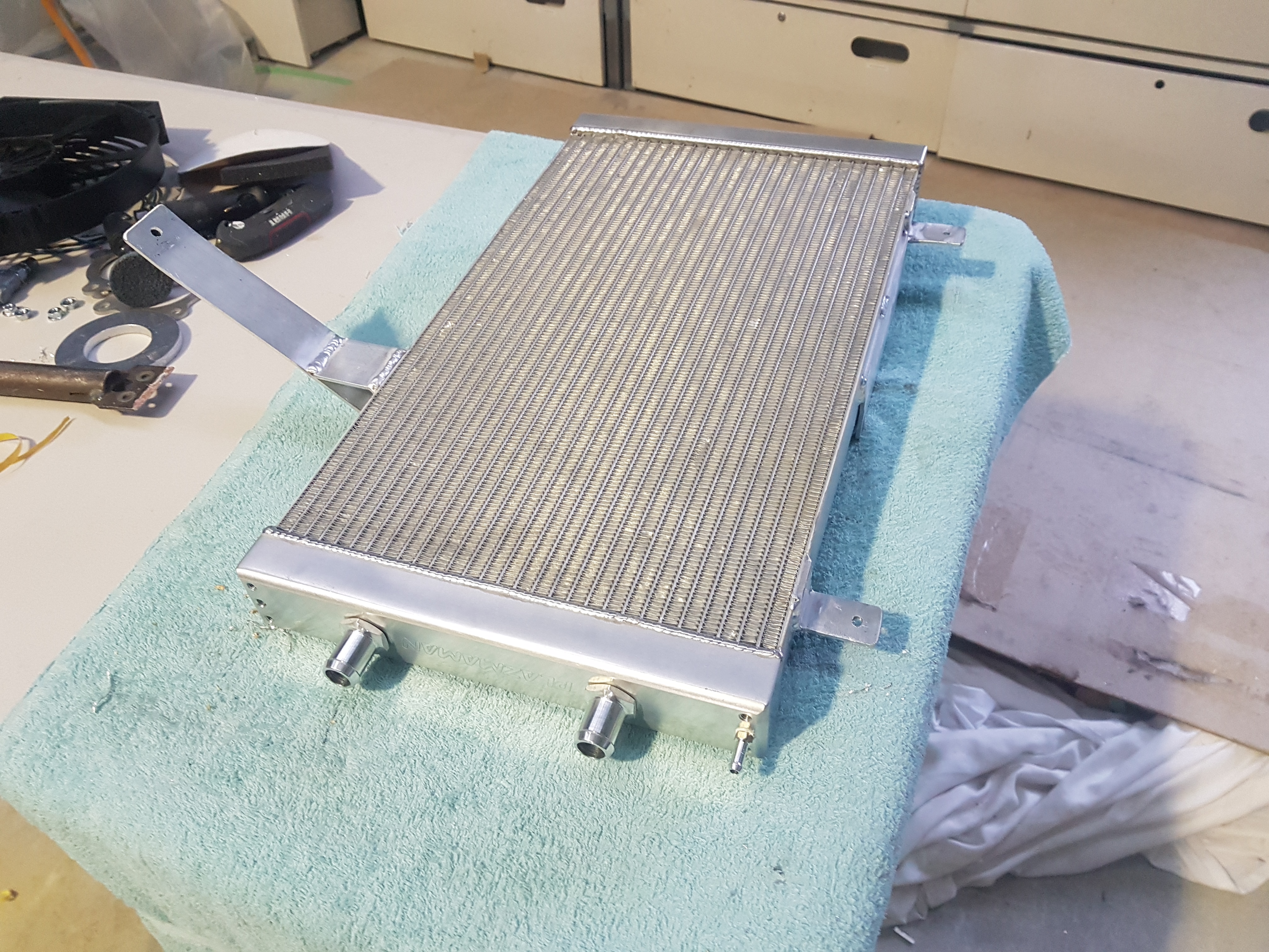
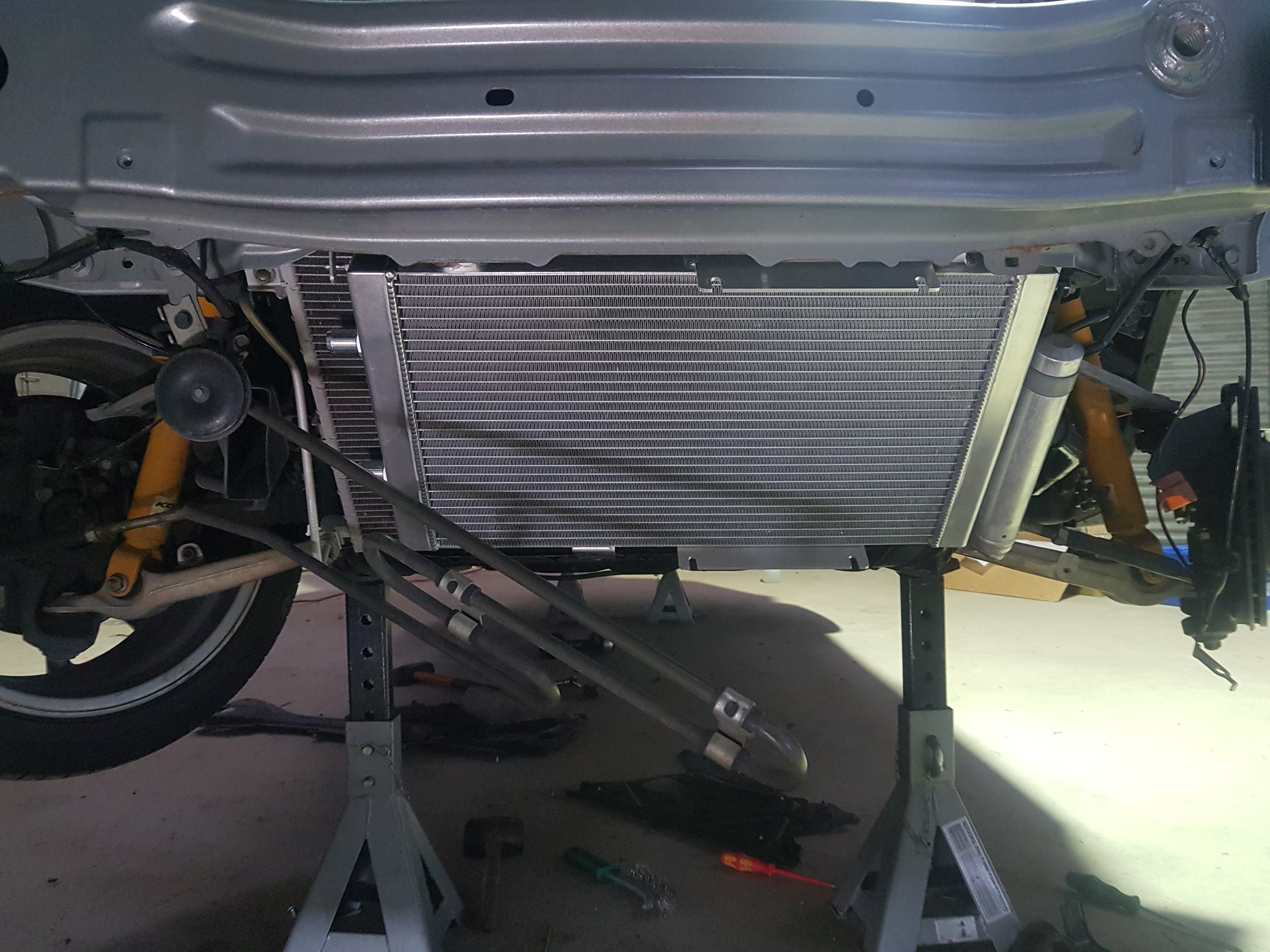
A radiator is required to cool the water from the intercooler and electric motor. For sufficient air flow it would be mounted in front of the factory radiator behind the front bumper. The radiator was sourced from Plazmaman. Mounting tabs were fabricated.
Plazmaman radiator with mounting tabsRadiator mounted
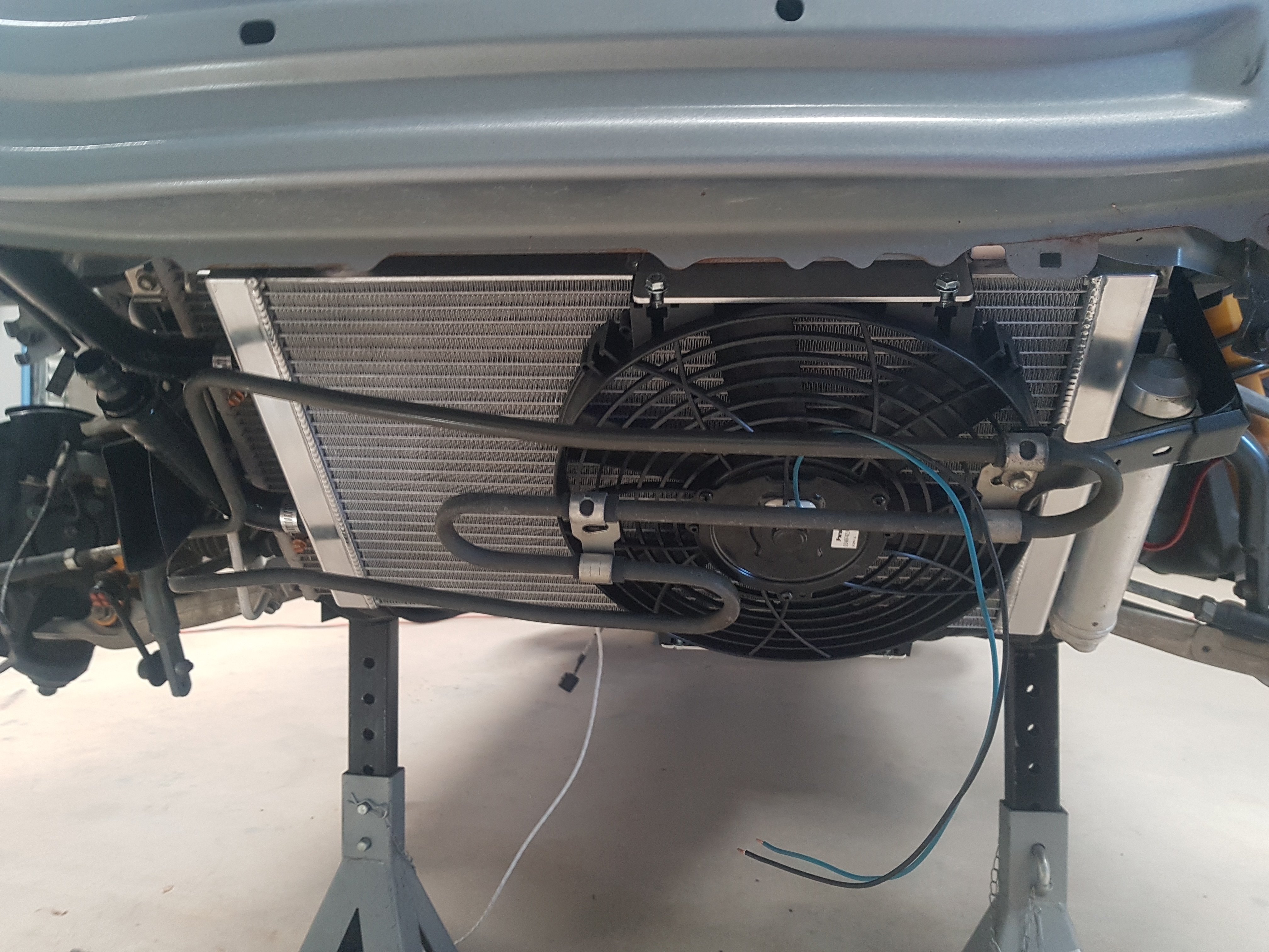
A cooling fan was added to the radiator. Then the mounting bracket for the power steering fluid cooling coil was modified so that it could be remounted in front of the new equipment
Cooling fan and power steering coil reinstated
Finally, the fan was wired in and coolant hoses were run from the radiator to the intercooler in the rear. These were routed through the engine bay and then on top of the PPF.
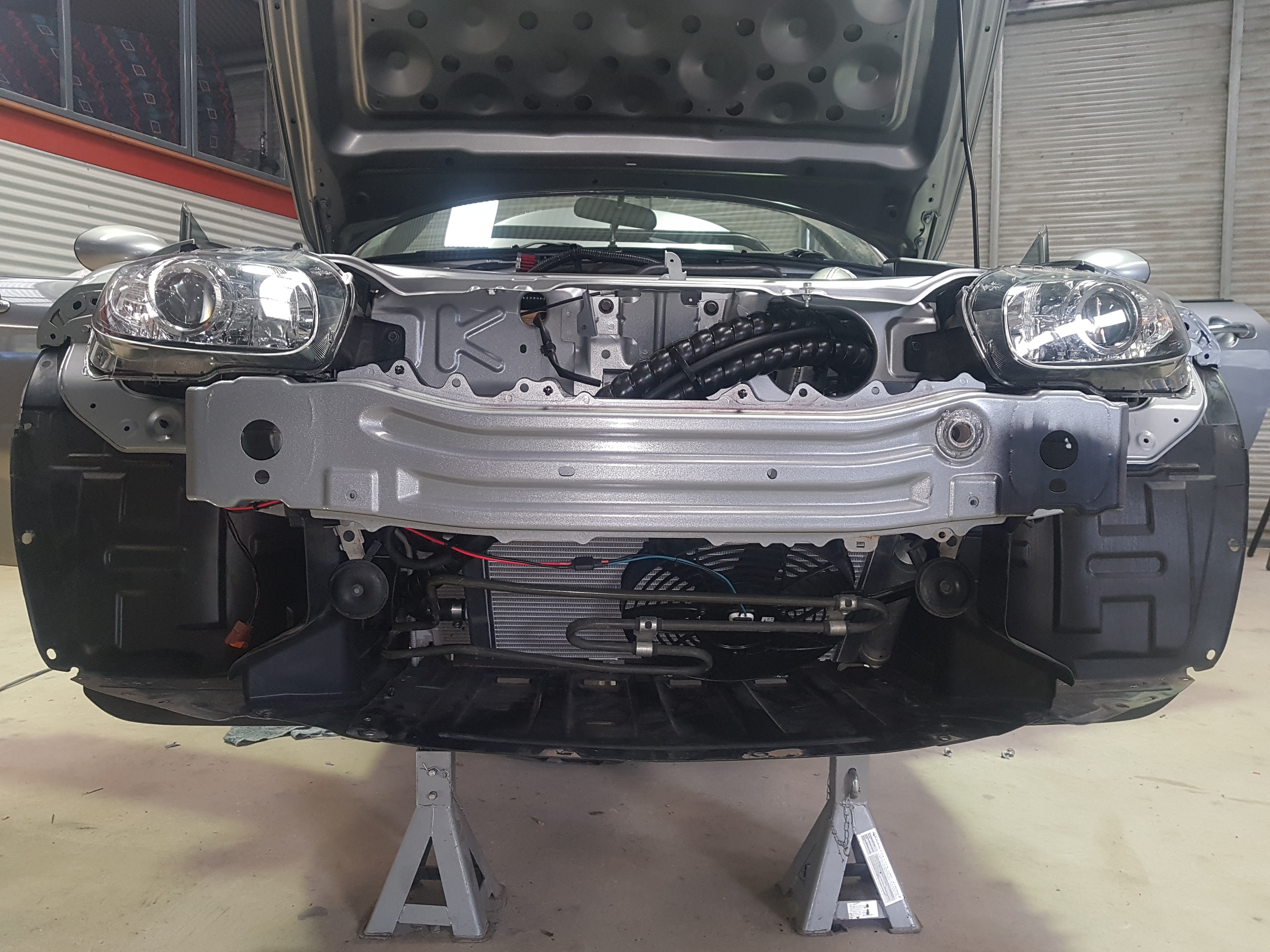
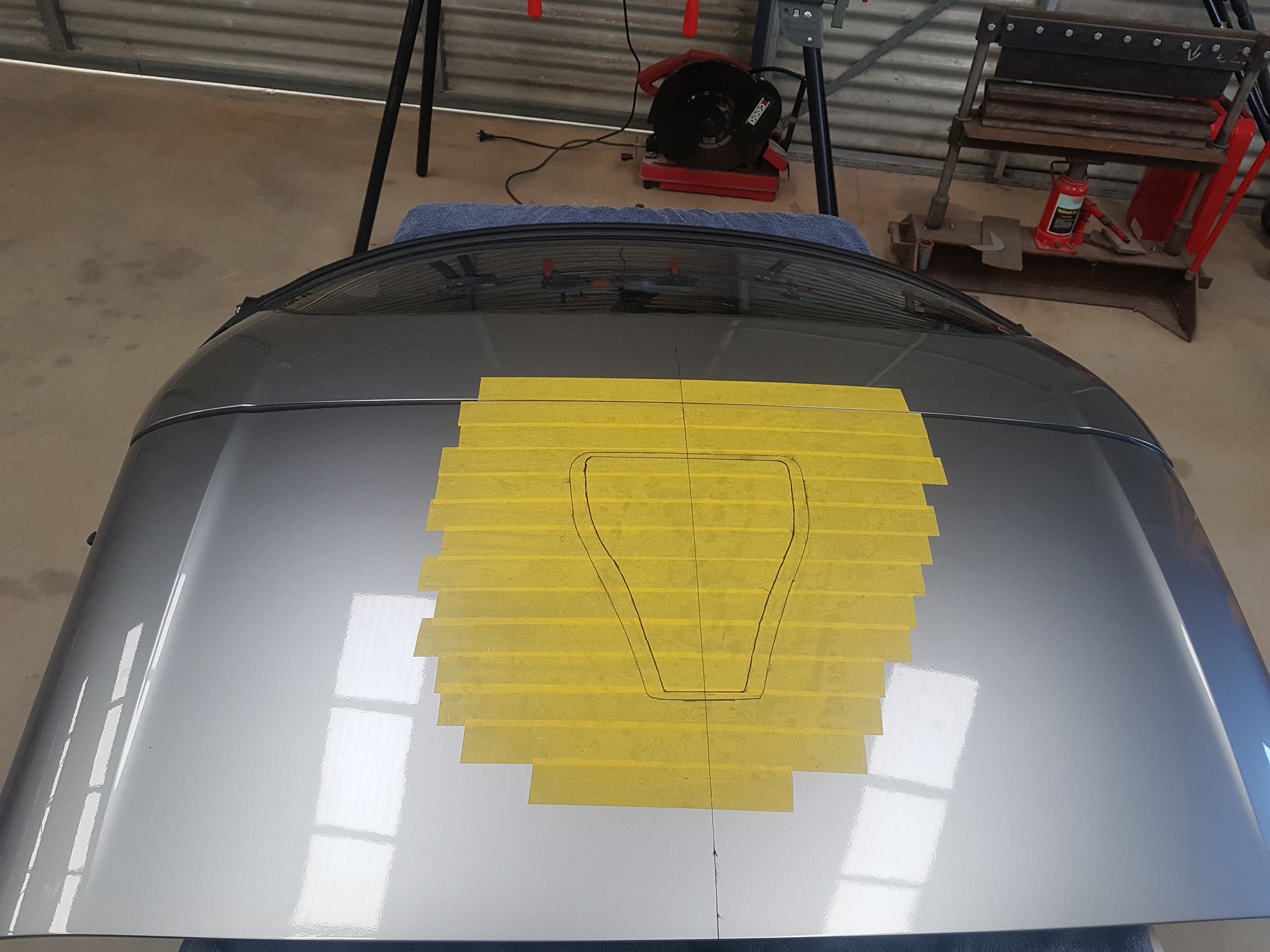
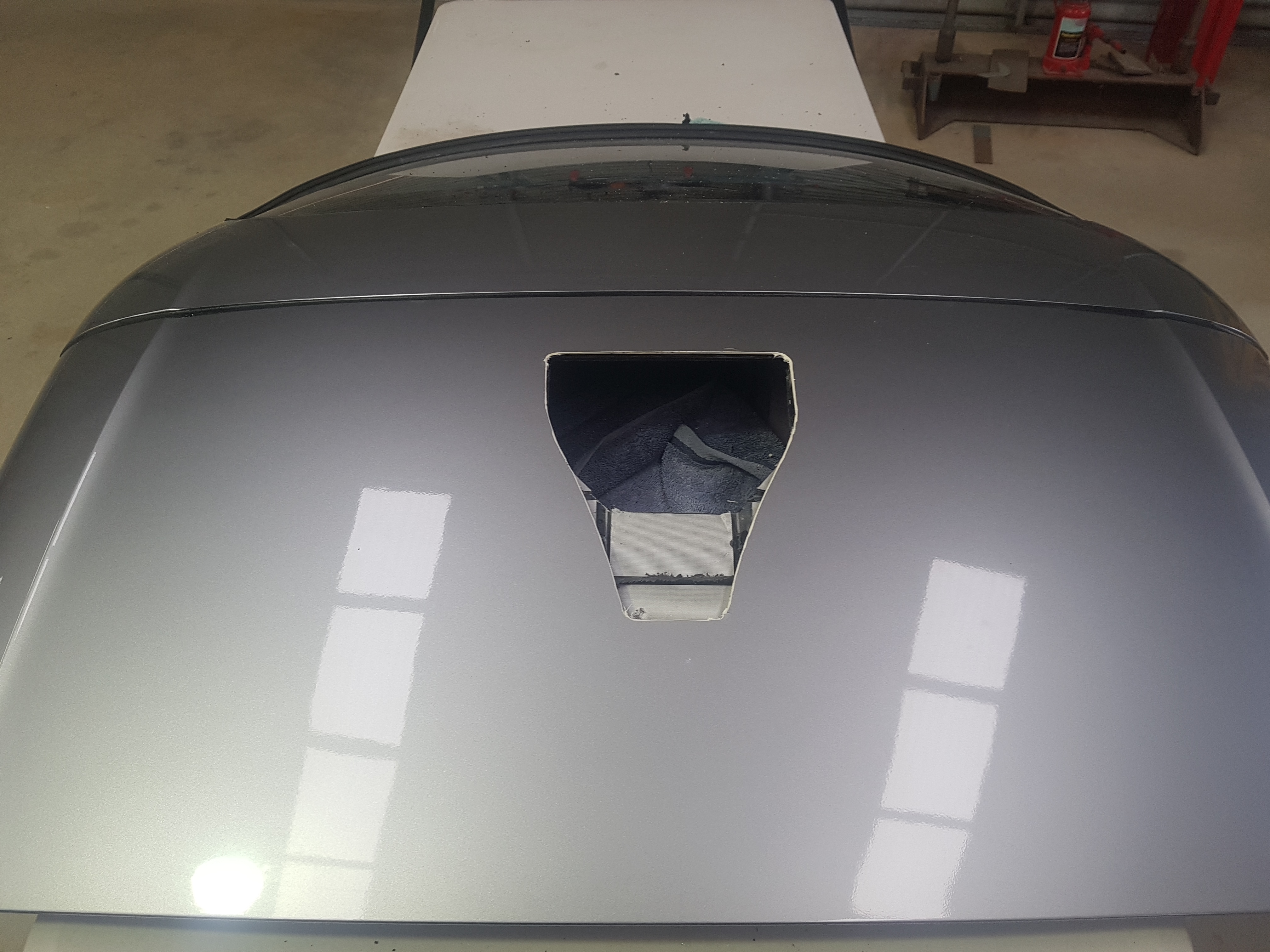
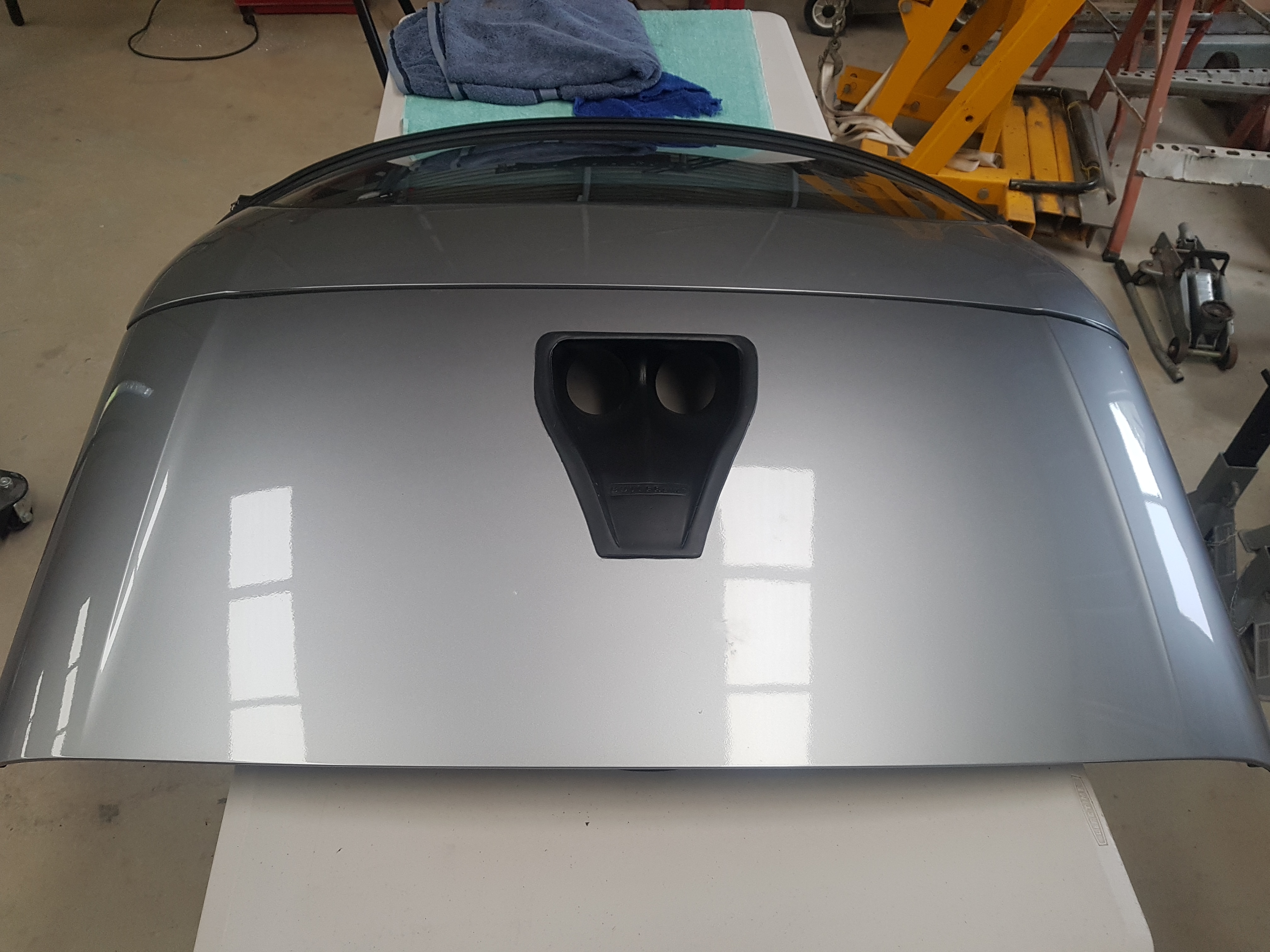
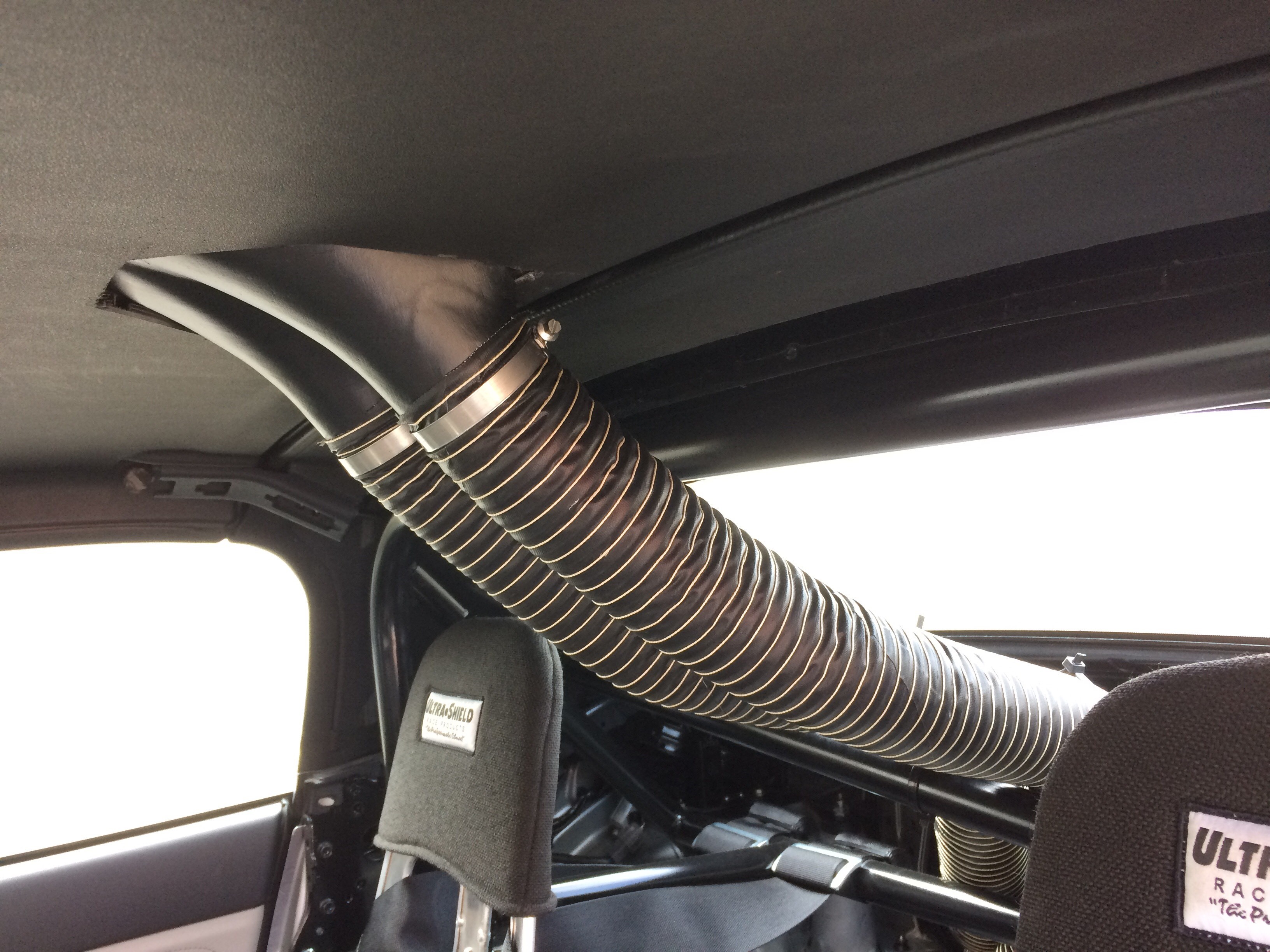
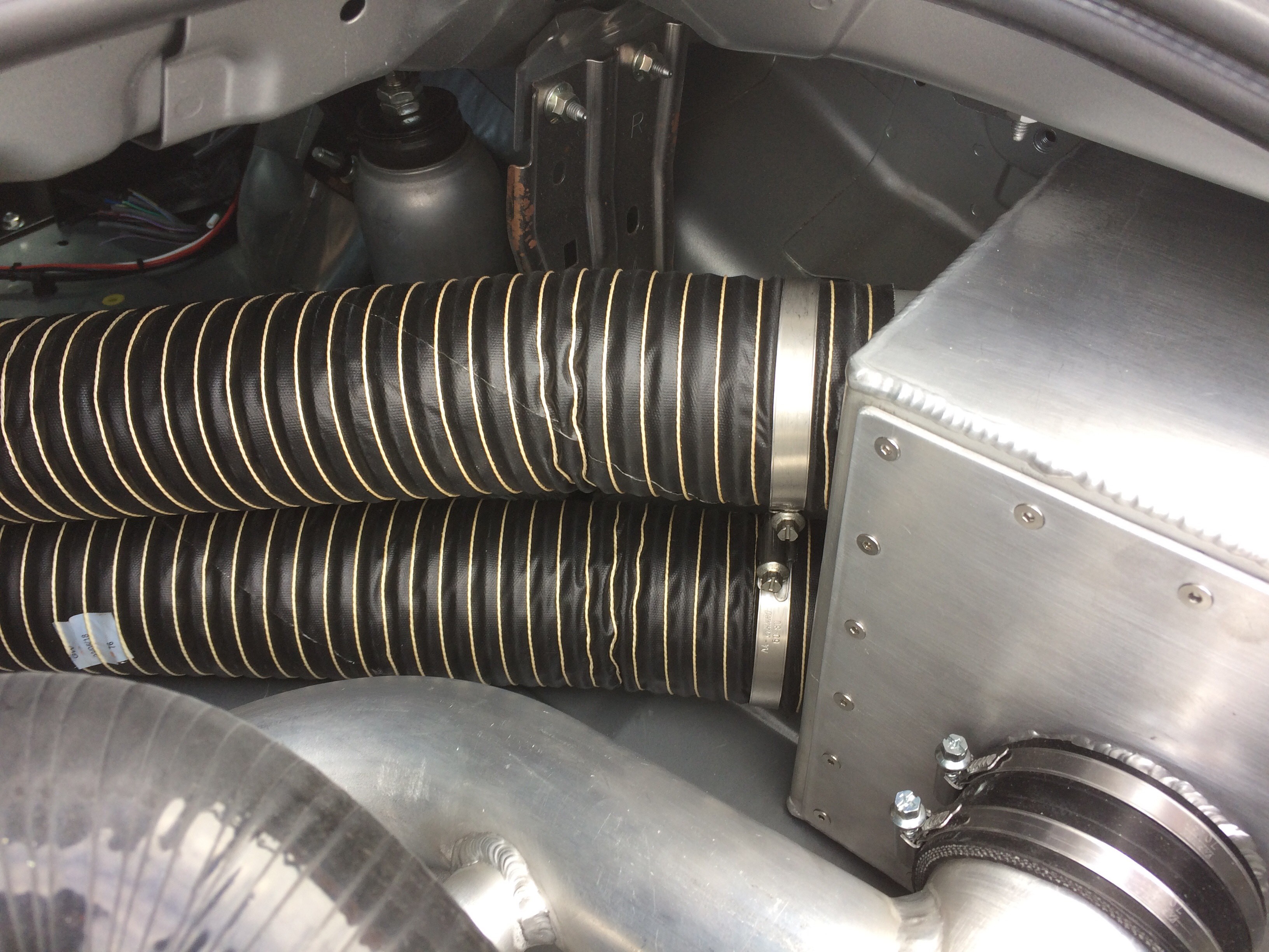
Fresh air needs to be channelled to the new air box. A lot of thought went into the location and type of duct to use. The final decision was to use a dual 3 inch NACA duct cut into the roof with 3 inch SCAT ducting connecting the NACA to the airbox.
Cut out markedCut out completeDual 3 inch NACA installedDual 3 inch SCAT hoseAir box connection
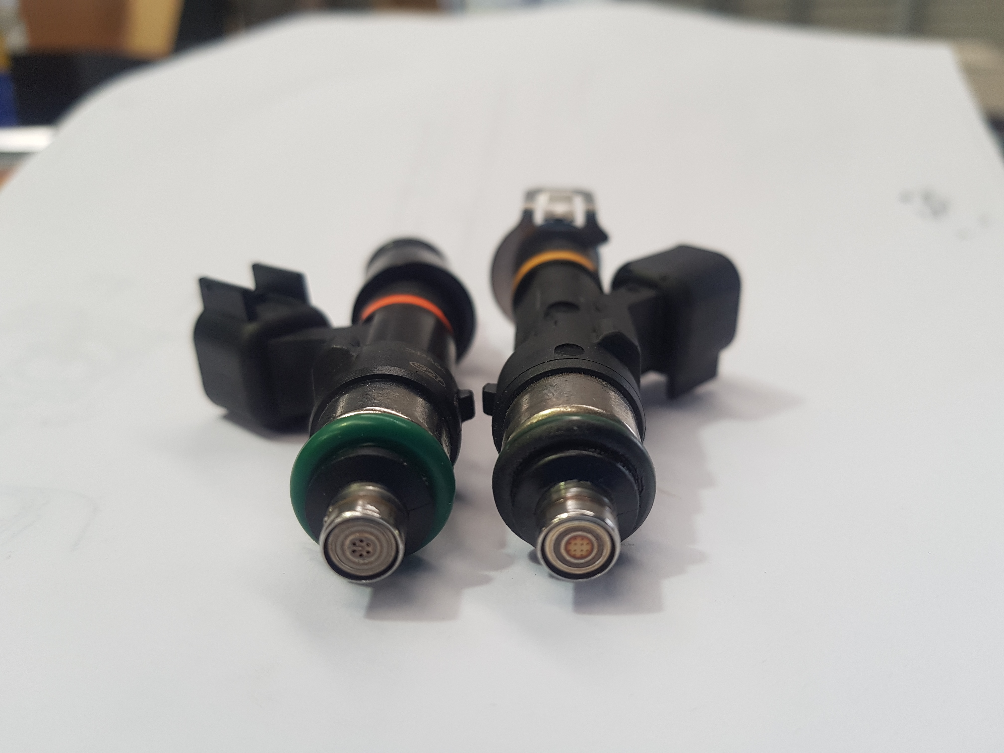
A few modifications are required to prep the engine for boost and higher air mass flow rates. The factory injectors were upgraded to Grams 550cc units to deliver more fuel. The factory fuel pump is good for 300 HP so it will be retained for now.
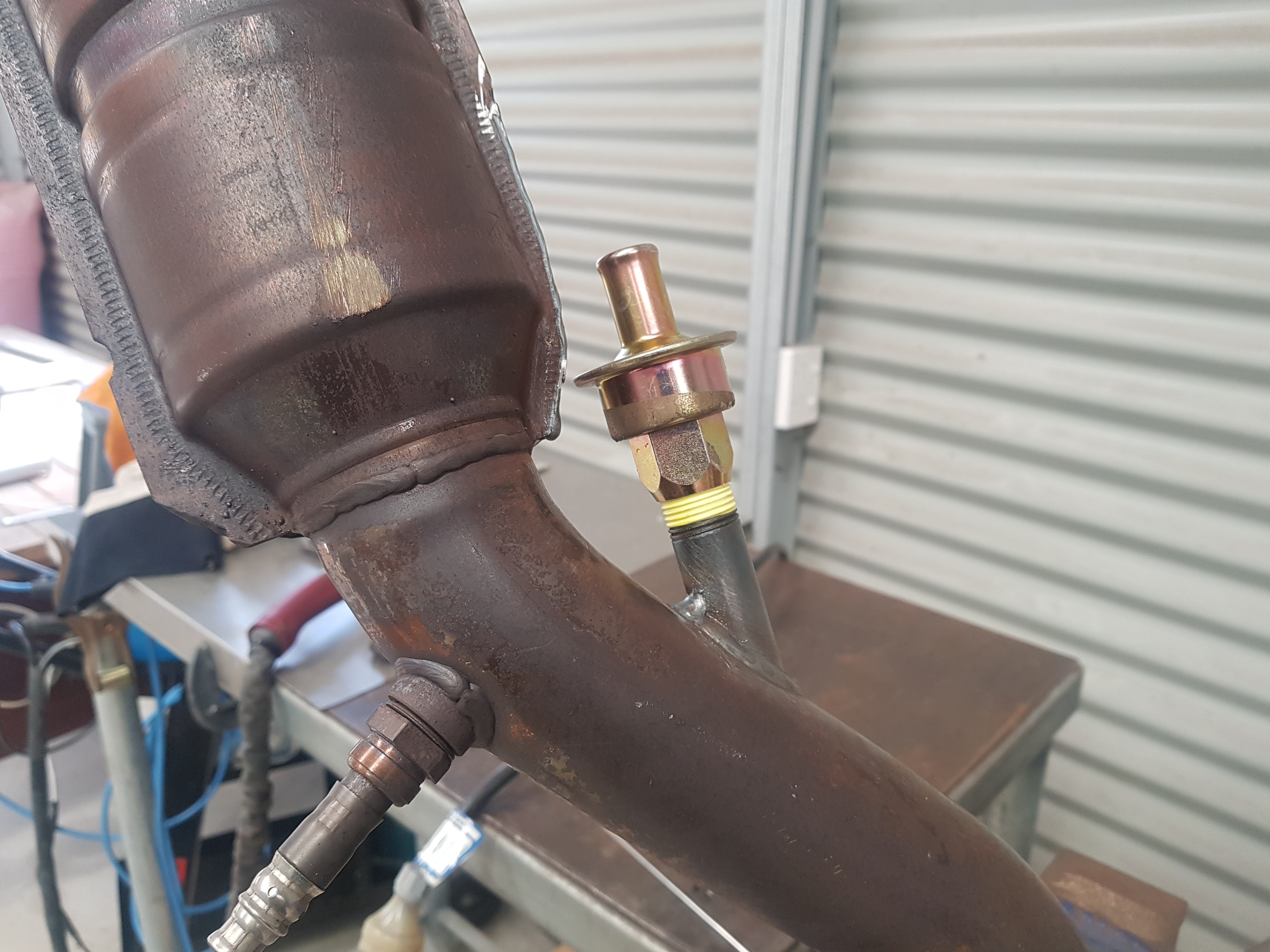
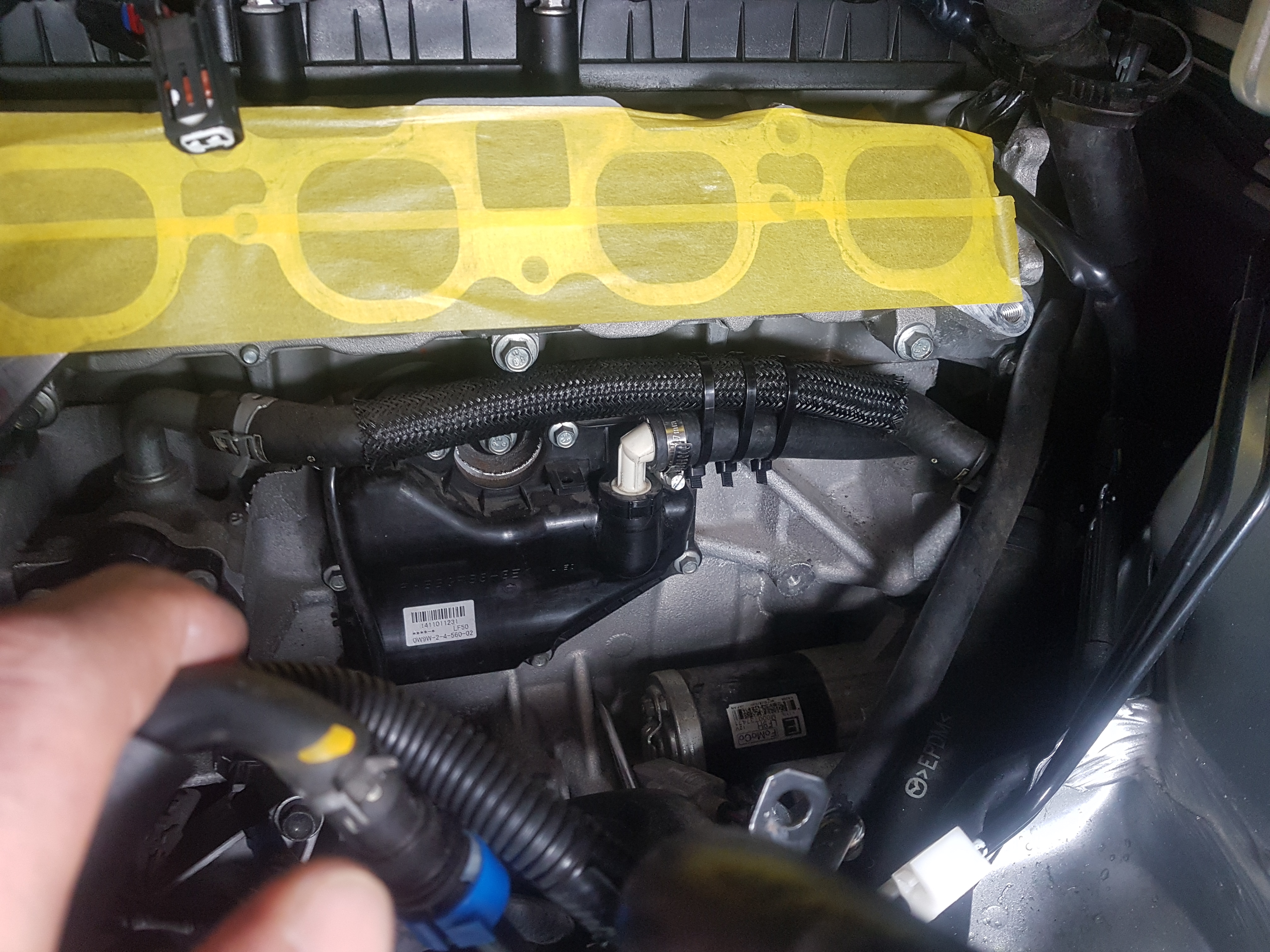
The factory positive crankcase ventilation (PCV) system does not deal well with boost. The inlet manifold dynamic chamber needed to come of which turned out to be a big job in itself. The hose between the PCV valve and the dynamic chamber was removed and the dynamic chamber end capped. A Moroso exhaust venturi and check valve were installed immediately downstream of the catalytic converter to create a vacuum and the PCV valve connected to the check valve.
PCV connection cappedMoroso venturi and check valvePCV valve plumbed back to venturi
Below is a quick video of the first spool up of the E-Charger in the vehicle. This was while we were filling and priming the oil circuit on the Rotrex compressor. First impressions is that system is surprisingly quiet with absolutely no vibration.