The finished product so far. Next will be to commission the e-charger system, load new tune into ECU, and begin testing.


The finished product so far. Next will be to commission the e-charger system, load new tune into ECU, and begin testing.
Factory ECU will be retained and tune adjusted using Ecutek re-mapping software. Mike form Moto East provided the new tune. After tune was loaded vehicle was taken for a drive and air/fuel mixture was very rich both on and of boost. Some logs were taken and sent to Mike. New tune with approx. 25% less fuel was received from Mike and loaded to ECU. Tune was much better and safe (AFR of 11.5 and ignition advance of 10 degrees on boost). Plan is to concentrate on ironing out the bugs in the E-charger control system before trying to optimise engine tune.


There were a number of control system bugs which were quickly resolved with some code modifications, however there were two bigger issues that became evident.
First, the Moroso exhaust venturi was not creating a vacuum, then after some driving the Moroso check valve failed. We are assuming that the venturi is not working due to it being installed downstream of the catalytic converter (should be installed in extractor collector) and being downstream and on the inside of a bend. The venturi cannot be moved upstream for fear of oil mist fouling O2 sensors and catalytic converter. The check valve diaphragm appears to have succumb to heat due to being installed to close to the cat. The check valve was removed and the venturi capped. The PVC will be vented to atmosphere until a solution is found. This may be an electric vacuum pump.
Secondly, when the system is running the boost drops significantly at higher engine speeds and loads. There is some concern that the recirculation valve is opening under higher boost pressures and flow rates as a differential pressure will developing between the outlet of the compressor (where the recirc valve is located) and recirc valve sense point at the engine intake manifold.
To eliminate this an electric solenoid valve will be installed in the recirculation valve sense line so that the valve is forced to the close position when the throttle position is above 50% open rather than relying on manifold pressure. This will be a hybrid electro-pneumatic system and will still use intake manifold vacuum to hold the bypass open at idle.
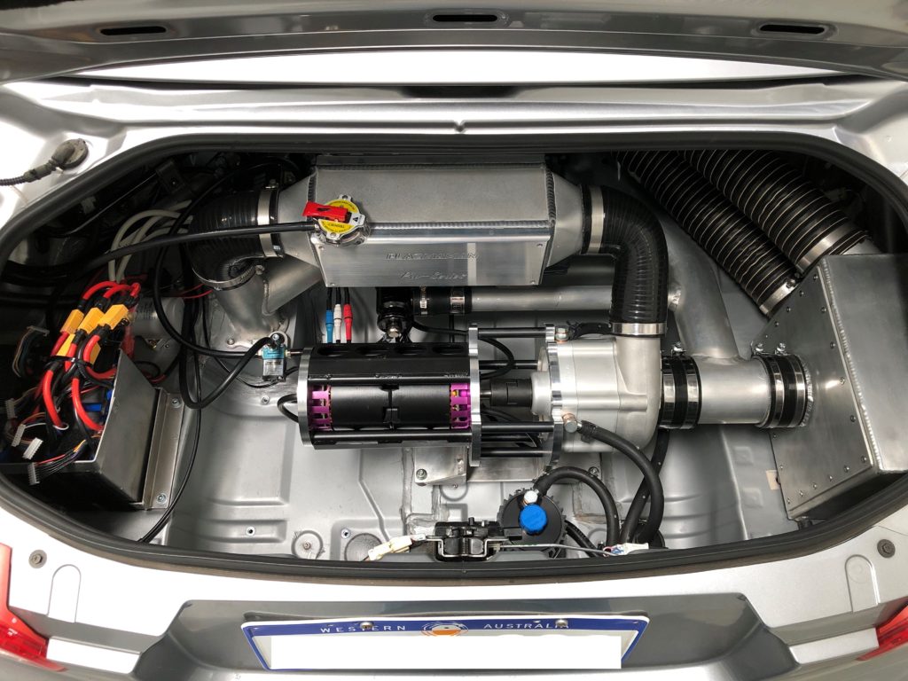
There is currently no boost pressure sensing point on the system in the rear of the vehicle. The intercooler was removed so one could be installed.

A turbo 3 port solenoid valve was sourced form Turbosmart. The valve is electrically connected to the PLC and equalises the pressure across the recirc valve when the throttle position is above 50% open. This insures the valve remain closed under boost.

We have been getting relatively high voltage drop between the battery and the ESC input power terminals during high current draw. The original design intent was to mount the control panel close to the battery and ESC in the rear of the vehicle. During installation it was decided that the best location for the control panel was behind the passenger seat meaning the cabling between the battery and ESC is approx. 2 meters long.
To eliminate the volt drop the power system cabling has been be upgraded by:


Testing so far has been limited to a maximum compressor impellor speed of 60,000 rpm. At this speed we are seeing boost pressures of 4.5 psi just of idle and approx. 1 psi at redline.
The system is being held back by the ESC for the following reasons:
It must be noted that ESC not being used for its intended design purpose and we asking quite a lot from it. Never the less it will need to be replaced with a more capable unit to unlock the potential of the system.
The MGM Controllers TMM 40063-3 was selected with the following specifications:


The cooling system required modification to add the new liquid cooled ESC to the circuit. At this time, it was decided to add two gear pumps to better control coolant flow through the electric motor and ESC.
The gear pumps are positive displacement and self-priming. The flow rate of the pumps will be fine tuned using an adjustable DC/DC buck converter. Pump suction is downstream of main coolant pump but before the intercooler. Coolant discharged from ESC and motor is plumbed back into coolant circuit after intercooler.

Also at this time the main cooling circuit pump was relocated to the front of the vehicle on the outlet of the radiator. This was done to get the pump as low in the circuit as possible to prevent it losing prime.

Lastly the electric fan has been added move air across the motor. The liquid cooling has been very effective at cooling the stator but the rotor has been getting quite hot. The fan will aid with keeping the rotor cool and prevent potential demagnetisation of the rotor magnets.

Starting to see some positive results from the ESC and cooling system upgrades. At the last event the car was very competitive. Compressor impeller speed was set to a maximum of 70,000 rpm. This impeller speed is good for 6 psi at low engine speed and 3 psi at redline. This gives good gains in low down torque and modest power gain at the top end.
We have had issues pushing past this impellor speed. Higher impellor speeds can be run for short periods (1st, 2nd, and 3rd gear pulls) but heat build-up in the motor and ESC are limiting use for longer periods in competition. The electric motor is not develop enough torque to drive the compressor at these high speeds and as the motor is synchronous the winding current peaks are very high. We have seen as high as 600 Amps on the motor winding.
The test data shows that the original calculations for required torque and power from the electric motor for a given boost level were understated due to some incorrect assumptions. On the up side the operating RPM range of the electric motor is perfect so decision has been made to add a second motor and ESC which will double our torque and help push up into the higher boost pressures.
First step was to develop a solution to get two electric motors driving the same shaft. This is not easily done due to the outrunner design and the cooling lines for the stator. Some 12mm round bar was sourced to make a common shaft to mount both rotors to and transmit power to the compressor. 4mm keyways were cut into the shaft and rotors and also for the drive coupler.


Next new plates were designed, drafted and CNC machined out of 10mm thick 6061 Aluminium.


The new plates will form the ends of a torque tube. To create the torque tube 4 standoffs were machined out of ½ inch round bar. Next bracing plates were manufactured out of 3mm mild steel plate and TIG welded to the standoffs.


For two motors it is necessary to run two electronic speed controllers. The second TMM 40063-3 ESC was stacked on top of the first.


To make room for the longer electric motor assemble the system battery had to be relocate.

Last step is to put it all back together.
Up until know the control of the electric motors driving the compressor has been quite basic. The speed controller input command has been tied to the foot accelerator pedal (linear relationship).
The problem with this approach is as engine RPM increases the boost pressure drops for a fixed speed controller input command. This is due to:
1. As mass flow rate increases compressor needs to be run at a higher speed to generate the same pressure ratio (as shown by compressor map)
2. As electric motor load and current increase battery voltage sages due to the internal resistance of the battery
The result is higher boost pressures at low engine RPM and lower boost pressures at higher engine RPM.
To even this out pressure control has been implemented. This was achieved by adding a pressure sensor (Haltech 3 bar MAP sensor) to the outlet of the compressor. This pressure signal is feed into the PLC were a PID control block manages the output to the electric motor speed controllers. This has proven very effective.
